Hi
I'm a complete novice with all things electrical & have developed a problem with a project that I started some time ago.
Basically I put a valve output stage in a Zero Dac, It all went well enough except I had a low level hum & hiss that I was keen to get rid of. I rebuilt the stage 3 times using different grounding etc.
It was during the 3rd build that my real problem emerged, once I had finished the third rebuild, I didn't have any signal from one channel.
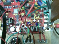
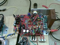
In the photos below I have put circles/eclipse around the signal stealing points where I have installed capacitor as per the design.
In my (novice) attempts to find the problem, the difference I can find in the two channels is that on the input side of the signal stealing capacitors, I have different voltages, the channel that is working has a voltage of 2.6v DC & the channel that is not is 0.4v DC. Is this likley to be where my problem is?
If you think this is the problem do you have any wild guess on what might be causing it? That's a big ask I know.
The only changes I made before the stealing points, was adding some capacitors that are piggy backed on the bottom of the board.
David
I'm a complete novice with all things electrical & have developed a problem with a project that I started some time ago.
Basically I put a valve output stage in a Zero Dac, It all went well enough except I had a low level hum & hiss that I was keen to get rid of. I rebuilt the stage 3 times using different grounding etc.
It was during the 3rd build that my real problem emerged, once I had finished the third rebuild, I didn't have any signal from one channel.
In the photos below I have put circles/eclipse around the signal stealing points where I have installed capacitor as per the design.
In my (novice) attempts to find the problem, the difference I can find in the two channels is that on the input side of the signal stealing capacitors, I have different voltages, the channel that is working has a voltage of 2.6v DC & the channel that is not is 0.4v DC. Is this likley to be where my problem is?
If you think this is the problem do you have any wild guess on what might be causing it? That's a big ask I know.
The only changes I made before the stealing points, was adding some capacitors that are piggy backed on the bottom of the board.
David
Attachments
Hi,
Keep the volume down. Take care HT Bites.
You could just touch your multi meter probe onto the output to amp connection and see if it buzzes this will tell if its an out put problem. if this is OK Then touch your multi meter probe onto the input to the tube circuit see if it buzzes:
You may have a fault on the connections on the circuit board so:
Swap the input to your non working side " At the tube circuit" ( NOT on the circuit board "PCB") over to the working side. If it works the fault is in the circuit you built if it dosen't its in the caps and connections on the circuit board.
Tell us what you get!
Regards
M. Gregg
Last edited:
Hi,
Keep the volume down. Take care HT Bites.
You could just touch your multi meter probe onto the output to amp connection and see if it buzzes this will tell if its an out put problem. if this is OK Then touch your multi meter probe onto the input to the tube circuit see if it buzzes:
You may have a fault on the connections on the circuit board so:
Swap the input to your non working side " At the tube circuit" ( NOT on the circuit board "PCB") over to the working side. If it works the fault is in the circuit you built if it dosen't its in the caps and connections on the circuit board.
Tell us what you get!
Regards
M. Gregg
Well
 who's the dummy then, I swapped the wires coming off the signal stealing points & sure enough the right side coming off the PCB is dead, which corresponds with the low voltage side.
 You would not believe how much time I spent trying to work out where the problem was. Initially I assumed it was on the valve side as that is the side I rebuilt 3 times.
I'm not sure what to do from here any suggestions?
Thanks for you help so far
")
David
2.6V DC at the output of the DAC chip seems right, but 0.4V DC does not. You could trace the point where you take off the faulty signal back to the DAC chip (the one marked CS4397) and measure the DC voltage directly on the chip pin. You should measure about 2.5V DC there which would mean the DAC chip is okay but there is an open circuit somewhere between it and the take-off point. If you measure 0.4V DC right off the DAC pin too, then the DAC is probably shot, or there is a short somewhere on the PCB.
Good luck.
Kenneth
Good luck.
Kenneth
2.6V DC at the output of the DAC chip seems right, but 0.4V DC does not. You could trace the point where you take off the faulty signal back to the DAC chip (the one marked CS4397) and measure the DC voltage directly on the chip pin. You should measure about 2.5V DC there which would mean the DAC chip is okay but there is an open circuit somewhere between it and the take-off point. If you measure 0.4V DC right off the DAC pin too, then the DAC is probably shot, or there is a short somewhere on the PCB.
Good luck.
Kenneth
Thanks for the input, my holidays are over so I probably wont get time to have a play until the weekend, I will let you know how I go.
David
Hi,
I would remove the piggy back caps you put on the board. Take the circuit back to the point when it worked! You may have caused a problem with the caps. I cannot tell are the caps electrolytic? If they are you don't have wrong polarity do you?
I would take off the caps on the non working side and see if you have a short from solder etc.
You could also swap the cable connections on the circuit board to eliminate a possible short on the cable, if the soldering iron has melted the insulation you may have a short to Gnd "screen".
Regards
M. Gregg
Last edited:
Hi,
I would remove the piggy back caps you put on the board. Take the circuit back to the point when it worked! You may have caused a problem with the caps. I cannot tell are the caps electrolytic? If they are you don't have wrong polarity do you?
I would take off the caps on the non working side and see if you have a short from solder etc.
You could also swap the cable connections on the circuit board to eliminate a possible short on the cable, if the soldering iron has melted the insulation you may have a short to Gnd "screen".
Regards
M. Gregg
Hi Gregg
The caps have been on from the start as they where the first things I put on, the unit played happily for some time until I tried to get rid of the hum yet again.
When you say "cable connectors" what cables are you referring to?
David
PS. I hope you don't follow the cricket, ouch.
Last edited:
2.6V DC at the output of the DAC chip seems right, but 0.4V DC does not. You could trace the point where you take off the faulty signal back to the DAC chip (the one marked CS4397) and measure the DC voltage directly on the chip pin. You should measure about 2.5V DC there which would mean the DAC chip is okay but there is an open circuit somewhere between it and the take-off point. If you measure 0.4V DC right off the DAC pin too, then the DAC is probably shot, or there is a short somewhere on the PCB.
Good luck.
Kenneth
Hi Kenneth
Well one of the DAC chip pins only measures 0.4V & the other 2.5V. I checked some of the capacitors I piggy backed before the DAC chip all of them have 5v across them except one which has 3.1V, maybe there is a problem before the chip.
I don't like playing with electricity at the best of times but especially after a hard day at work & when I'm tired, so I might leave further investigations until the weekend.
Thanks
David
David,
Have you drawn up a schematic for the tube output stage? It would be helpful if you could post that.
Kind regards,
Bas
Yes I have, but that is not where the problem lies, its in the PCB which is before the output stage.
I also feel a bit funny posting it as it is not really mine to post, I just turned a badly done sketch into a novices schematic. I did fix a couple of problems though. I'm not sure what the protocol is for such things.
David
If you found it on a publically-accessible website, I wouldn't worry about that. The artwork is yours -- just acknowledge the original circuit's author.
As to the problem at hand -- I'm still worried about that 0.4V. Could you measure the voltages on all analog pins of the DACs (all outputs and VREF)? Just grab the DAC's datasheet for the pin-out.
EDIT - Possibly also with the capacitors removed?
Kenneth
As to the problem at hand -- I'm still worried about that 0.4V. Could you measure the voltages on all analog pins of the DACs (all outputs and VREF)? Just grab the DAC's datasheet for the pin-out.
EDIT - Possibly also with the capacitors removed?
Kenneth
Hi Gregg
The caps have been on from the start as they where the first things I put on, the unit played happily for some time until I tried to get rid of the hum yet again.
When you say "cable connectors" what cables are you referring to?
David
PS. I hope you don't follow the cricket, ouch.
Hi,
I was refering to the cable solder connections on the PCB.
The cable may be at fault disconnect the cable from the PCB "caps" see if the voltage comes up. Or reconnect the good cable to the "bad side" on the PCB and see if it works.
If all else fails remove the caps you put on and see if the voltage comes up to match the other side!
When fault finding you must not assume anything is "good". If your tube circuit works on both sides you have to eliminate "remove" everthing that is not part of the PCB and see if the PCB functions. Is there an audio out on the PCB? if there is, forget the tube circuit and get the PCB working as it should with no "soldered on" parts.
Just looking to eliminate possible causes the easy way.
Regards
M. Gregg
Last edited:
- Status
- This old topic is closed. If you want to reopen this topic, contact a moderator using the "Report Post" button.
- Home
- Amplifiers
- Tubes / Valves
- Novice In Over His Head