So it is ok to have your star ground point "floating" as long as it is connected to the chassis through a cl-60?
I just want to be sure.")
Yes that's fine...but what do I know
Well, made my first Gerbers ever, got it on the second try, first try no component numbers and text on silkscreen was shown and the drill data was missing. But got it on the second try.
Anyone who can wiev Gerbers who could take a peek and see if it looks ok?
Anyone who can wiev Gerbers who could take a peek and see if it looks ok?
Attachments
So it is ok to have your star ground point "floating" as long as it is connected to the chassis through a cl-60?
I just want to be sure.
thats how its shown in all of Nelson's FirstWatt manuals, and F5
I think one "commercial" reason for having star ground placed on either supply board or amp board is for convenience
its easier to "descibe" and "handle"
its very similar to "old style" star ground, where all grounds were connected to chassis bottom by a bolt
only, now its "dissconnected/isolated" from chassis
practically, you could use a thick solid core copper wire to speaker ground(minus), and solder other ground connections directly onto that wire
yes, it is. Connect your chassis direct to protective earth. Then connect chassis to the star point through a CL-60.So it is ok to have your star ground point "floating" as long as it is connected to the chassis through a cl-60?
I just want to be sure.
Ground loops are usually caused by very small potential differences.
So it is all about V=IR or I=V/R. If the resistances are small between the two points then large currents flow causing hum. However if you increase the resistance between the two points the currents are small causing no hum.
1. I=0.1/.1 = 1A
2. I=0.1/10 = 0.01A So adding a thermistor makes a big difference
Last edited:
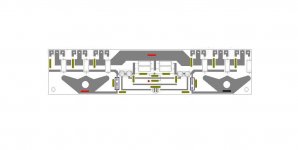
this layout will be very easy to hardwire on veroboard
its only half done, so please look out for possible errors
ofcourse its free to use in part, or as is, or just for inspiration
others here will most likely do a better job than I
It have been requested earlier that I should finish my drawings a bit better, with parts numbers etc
I will work on that
its only half done, so please look out for possible errors
ofcourse its free to use in part, or as is, or just for inspiration
others here will most likely do a better job than I
It have been requested earlier that I should finish my drawings a bit better, with parts numbers etc
I will work on that
Attachments
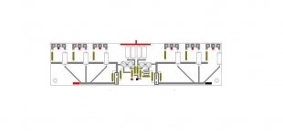
One thing came to mind the 2 input fet shuld be close togheter and the casing thermaly coupled
so temperature track both channels
yes, they should, but you cant have it all
my goal is a simple logic layout where most parts legs can reach other, hardwired
and thus trying to avoid "complicated" layout
my original plan was to couple them through a block of alu
might not effectively couple them together
but it will keep them cooler
and it might also serve as shielding
thats why they are placed in line
but true
once you try to put it all on a veroboard, it might be possible to make it much more compact, and achieve what you suggest
hardwired has the advantage of working in many "levels", or should I say multiple 3 dimensional layers
but it would look very messy on a drawing
I would suggest to try and put some cheap components together
not a working proto, so values doesnt matter
only as a "layout" exercise
Hi tinitus
Block of alu is ok but it will increase the time it takes them to setle to operating temperature will try to post a couple of pictures tomorow
On ground loops I have found more material on the folowing link
Ground loops, earth hums, buzz and interference. Free data sheet by GB Audio Services
I still dont think that 10 or 20 ohms the nominal resistance of the thermistors is enough to stop a ground loop
With my F5 I have found thermally coupling the input jfets together unecessary. However it is probably not a bad idea.
If one thermistor is not enough you can always put another in series.
If that is not enough then the bridge rectifier approach is the way to go. This completely isolates until the diodes turn on.
If one thermistor is not enough you can always put another in series.
If that is not enough then the bridge rectifier approach is the way to go. This completely isolates until the diodes turn on.
With my F5 I have found thermally coupling the input jfets together unecessary. However it is probably not a bad idea.
Right so
I guess most F5 built here are all working fine without the thermal coupling
but its certainly a challenge
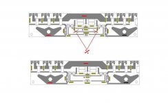
so I tried to crumple it a bit more, and almost there now Attachments
the loop in the ground is still there, we can all see it.So if you put a cl-60 from psu gnd to chassis ground like the power supply example in the F5 manual, then the ground loop will be gone?
The current flowing in the loop is massively reduced by the added resistance of the CL60.
A cold CL60 has about 10000 times the resistance of a piece of wire capable of passing worst case fault current.
So, let's say with the direct wire connection in place we have 1mVac @ 50Hz and another 1mVac at higher frequencies upto RF.
The direct link is ~ 1milliohm. The ac currents that flow are ~1mA of 50Hz and ~1mA of higher frequencies.
Now insert the CL60.
The two circulating currents are reduced <<1uAac.
The other circuits connected to different parts of the loop will only be affected by the voltage drop across their bit of the loop, say 0.1milliohm between two reference tappings and 1uAac flowing creates a difference in reference voltage of ~1nVac, instead of 10000nVac.
posts 9655 and 9657 showing the star ground separated from the PSU caps are both perfect.
They agree with
http://www.diyaudio.com/forums/diya...udio-component-grounding-interconnection.html
The separation does not need to be big.
The shorter all the connections from client circuits to the Star (main) Audio Ground, the better.
The PSU cap to star ground separation can be 1mm, yes that works.
Sugden have the PSU cap traces on one side of the PCB and a nut and bolt through the PCB make the connection to the Audio Ground on the other side of the PCB. The separation is the thickness of the PCB used ~1.4mm.
Last edited:
Do you "think" or have you actually tried?I still dont think that 10 or 20 ohms the nominal resistance of the thermistors is enough to stop a ground loop
Ground loops are a problem caused by small differences in resistance, so put those 10 ohms in perspective.
Hi Andrew,
I've built Cvillers F5 & PS boards and I haven't finished the chassis. I noticed the amp boards have INgnd, Vgnd and OUTgnd on them. And the PS board has outputs for ground which would be convenient to wire to the amp boards.
I imagine the best way would be to have a star ground and run everything to that instead of using the recommended wiring scheme to daisy chain everything together?
I guess it's okay for the INgnd and Vgnd to share the same GND?
Also if I use the star ground for the speaker minus does the wire quality of the minus make a difference?
- Home
- Amplifiers
- Pass Labs
- F5 power amplifier