At last someone who knows what he's talking about!
What i have discovered so far is some folks lack of knowhow when it comes to implementing TPC which has led to patently false comparisons with TMC.
The same folks have failed to appreciate that TMC is related to TPC more closely than they accept, and that TMC is a poor relative of TPC.
Hi Mike,
Yes, megajocke certainly knows what he is talking about, and his results are impressive and insightful. It is indeed useful that he has shown that the addition of an appropriate lead network in the feedback path can make TPC act similarly to TMC.
However, this certainly does not mean that the others here have a lack of knowhow, and you are insulting them by suggesting that. Moreover, I say once again, TMC is equal to or better than TPC and at the same time it does not require a lead circuit in the feedback path to make it so.
This may be a subjective matter, but I do not agree with your conclusion that TPC and TMC are closely related; they are not.
Finally, all of the evidence so far indicates that TMC is certainly not a "poor relative" of TMC. I consider it to be superior to TPC, and so do Baxandall and Self. You are on the wrong side of the fence on this one and are just being stubborn about it.
Cheers,
Bob
Santa brought me your book , Bob. Not to patronize , but I like it more than Self's book  . The basic amplifier examples (explained basically) are augmented by the theory behind them in the same paragraph , for me, the best and most practical layout for a technical publication. Lot's of MOSFET "stuff " ,too !!
TMC vs. TPC ?? I tried TPC , went back to traditional 1 cap miller comp. ... not a justifiable sound improvement to be had with TPC. TMC , on the other hand , is VERY noticable on a "blameless" at high output levels. "Best Bang for the buck(cap)" Practically , TMC is the clear winner here (I build to keep, don't like to throw good FR-4 away).
OS
. The basic amplifier examples (explained basically) are augmented by the theory behind them in the same paragraph , for me, the best and most practical layout for a technical publication. Lot's of MOSFET "stuff " ,too !! TMC vs. TPC ?? I tried TPC , went back to traditional 1 cap miller comp. ... not a justifiable sound improvement to be had with TPC. TMC , on the other hand , is VERY noticable on a "blameless" at high output levels. "Best Bang for the buck(cap)"
Practically , TMC is the clear winner here (I build to keep, don't like to throw good FR-4 away).OS
Santa must have a stockpile because he slid one my way as well. I read the Ch on compensation and will re-read it several times in the end. The facts you reference in the book does clearly suggest TMC has advantage over standard 2 pole assuming a properly designed amplifier.
Referring to the section on HEC for mosfets, have you ever considered using bootstraps for the driver section and powering that stage from the mosfet drain supply and using the higher voltage regulated supply for the VAS and IPS for only the pre-drivers and error amp section? This way there would only be need for a few mA on the high voltage tier and the drivers would be powered by the output stage above Vdd minus the bootstrap resistor voltage. And they would be sort of cascode.
I like the format of the book, it is very text book style and easy to comprehend for those of us who have background. If only it were hardback turning the pages back and forth for the reference graphic to the text it would not be so hard on the book pages. I guess Santa has limited resources. Thats OK, content is more important to a book. It is obvious that this book was not written overnight and you put some considerable time into it.
Its great Bob thanx
Chris
I read the Ch on compensation and will re-read it several times in the end. The facts you reference in the book does clearly suggest TMC has advantage over standard 2 pole assuming a properly designed amplifier. Referring to the section on HEC for mosfets, have you ever considered using bootstraps for the driver section and powering that stage from the mosfet drain supply and using the higher voltage regulated supply for the VAS and IPS for only the pre-drivers and error amp section? This way there would only be need for a few mA on the high voltage tier and the drivers would be powered by the output stage above Vdd minus the bootstrap resistor voltage. And they would be sort of cascode.
I like the format of the book, it is very text book style and easy to comprehend for those of us who have background. If only it were hardback turning the pages back and forth for the reference graphic to the text it would not be so hard on the book pages. I guess Santa has limited resources.
Thats OK, content is more important to a book. It is obvious that this book was not written overnight and you put some considerable time into it. Its great Bob thanx
Chris
Looking at the last page of megajocke demonstration,
it seems to me that the lead compensation is connected
between the OPS output and the Vas input, which amount
to introduce a dose of TMC...
If this is the case, it s no more TPC in its own right, but rather
a mix of the two, call it TMTPC or TPTMC if you like....
it seems to me that the lead compensation is connected
between the OPS output and the Vas input, which amount
to introduce a dose of TMC...
If this is the case, it s no more TPC in its own right, but rather
a mix of the two, call it TMTPC or TPTMC if you like....
Attachments
Looking at the last page of megajocke demonstration,
it seems to me that the lead compensation is connected
between the OPS output and the Vas input, which amount
to introduce a dose of TMC...
If this is the case, it s no more TPC in its own right, but rather
a mix of the two, call it TMTPC or TPTMC if you like....
Yes, an obvious point needs to be made - that TMC is an example of nested feedback whereas pure TPC is merely enhanced GNFB. Even when applied to a 3 stage amplifier the difference is not insignificant.
Hi Mike,
Yes, megajocke certainly knows what he is talking about, and his results are impressive and insightful. It is indeed useful that he has shown that the addition of an appropriate lead network in the feedback path can make TPC act similarly to TMC.
That is, almost act similarly to TMC. See post 1226.
However, this certainly does not mean that the others here have a lack of knowhow, and you are insulting them by suggesting that.
This so called "lack of knowhow" stems rather from the fact that we don't want to waste our time on optimizing that 'ugly travesty'.
Moreover, I say once again, TMC is equal to or better than TPC and at the same time it does not require a lead circuit in the feedback path to make it so.
This may be a subjective matter, but I do not agree with your conclusion that TPC and TMC are closely related; they are not.
Finally, all of the evidence so far indicates that TMC is certainly not a "poor relative" of TMC. I consider it to be superior to TPC, and so do Baxandall and Self. You are on the wrong side of the fence on this one and are just being stubborn about it.
Cheers,
Bob
Hi Bob,
I agree with all your points, except your remark about the lead circuit in the feedback path. It's certainly not a subjective matter. With such a circuit, the unity loop gain frequency at the inverting input of the IPS becomes two to three times higher. Maybe it doesn't matter, though I think it does matter.
If it really doesn't matter, then we could safely lower the TMC caps accordingly and get a much better performance. OTOH, if it does matter, then we must increase the TPC caps and, consequently, get less performance from that 'ugly travesty'.
In either case, TMC will be the clear winner.
Cheers,
E.
Last edited:
Santa brought me your book , Bob. Not to patronize , but I like it more than Self's book
TMC vs. TPC ?? I tried TPC , went back to traditional 1 cap miller comp. ... not a justifiable sound improvement to be had with TPC. TMC , on the other hand , is VERY noticable on a "blameless" at high output levels. "Best Bang for the buck(cap)"
OS
Hi ostripper,
Thanks for those very kind words about my book, and I hope you enjoy it as you read it. Please keep me posted on any goofs you find.
I'm excited to hear of your positive results with TMC. I really do believe that it is a well-behaved, good-performing technique. I also think that the spirited debate that we have had here has been educational to all of us, and that it has improved our understanding of how TMC and TPC work. This will probably result in better designs of each, whichever approach one chooses.
Cheers,
Bob
the Designer has the right to make choices !............. TMC and TPC work. This will probably result in better designs of each, whichever approach one chooses.
Just a few questions ,Bob . Your example amp in chapter 3.8 /figure 3.14 looks EXACTLY like my AX/PB250 but with a triple. You also say it can produce 580W/2R .
That seems to be on the "hairy edge" for both the MJE15032/33's and the 4 pair MJL21193/4 OP's with SOA considerations. At best that would be 1 second on the MJL's SOA at 65-70V rails. I actually am going to build this example as a triple with OPS= 2sa1381/c3503 (pre) - njw0281/0302 (To-3p driver) - 6 PAIR NJW21193/4 (to-3p OP's) for my subwoofer amp project. Am I just going overboard , or is the example just a tad over-rated ?
PS. I am not "picking" , but I really have this amp (below - 4X njw21193/4) , and would not run it at 580w !! A very worthwhile design that runs flawlessly ... but not at 580w !
BTW , simulated THD20 this amp does .008% at 580W w/TMC .
.That seems to be on the "hairy edge" for both the MJE15032/33's and the 4 pair MJL21193/4 OP's with SOA considerations. At best that would be 1 second on the MJL's SOA at 65-70V rails. I actually am going to build this example as a triple with OPS= 2sa1381/c3503 (pre) - njw0281/0302 (To-3p driver) - 6 PAIR NJW21193/4 (to-3p OP's) for my subwoofer amp project. Am I just going overboard , or is the example just a tad over-rated ?
PS. I am not "picking" , but I really have this amp (below - 4X njw21193/4) , and would not run it at 580w !! A very worthwhile design that runs flawlessly ... but not at 580w !
BTW , simulated THD20 this amp does .008% at 580W w/TMC
.Attachments
Last edited:
Santa must have a stockpile because he slid one my way as well.
Referring to the section on HEC for mosfets, have you ever considered using bootstraps for the driver section and powering that stage from the mosfet drain supply and using the higher voltage regulated supply for the VAS and IPS for only the pre-drivers and error amp section? This way there would only be need for a few mA on the high voltage tier and the drivers would be powered by the output stage above Vdd minus the bootstrap resistor voltage. And they would be sort of cascode.
I like the format of the book, it is very text book style and easy to comprehend for those of us who have background. If only it were hardback turning the pages back and forth for the reference graphic to the text it would not be so hard on the book pages. I guess Santa has limited resources.
Its great Bob thanx
Chris
Hi Chris,
Glad you like the book! BTW, speaking of text book issues, I am looking into the possibility of getting the book into some academic applications, particularly audio engineering vocational schools and community colleges. I think it is important to get young people education in electronics and analog design, and in some cases if audio is the hook, some more students may be drawn to it.
By bootstrapping the drivers, I assume you mean by means of capacitors from the output. If that is correct, then the answer is no. I don't generally use capacitive bootstrapping. I do seem to recall that Halcro uses some bootstrapping of some sort in their error correction circuit that was a derivative of my original design.
Cheers,
Bob
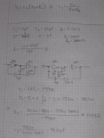
Hi Joakim,
Thx for the derivations. The transformation is correct, except for thing: the loading on the VAS output. Between 10 and 100kHz it is ~10dB higher. As a result, somewhat higher THD20.
Cheers,
E.
Yes, the loading on the VAS and its local feedback is different. I was only looking for a network with the same input-to-output and feedback-to-output transfer functions.
However, it is possible to replace the TPC network afterwards with another one giving the same VAS transimpedance. Use for example the values 2 x 28 pF and 4 kohms that was used in Bob's TPC simulation which loads the VAS less but gives the same transimpedance.
With these values I got distortion a tad lower for TPC+lead than TMC in the simulation. Perhaps it's the decreased signal level at the LTP that makes up for the increased loading of the VAS. Especially as the loop gain around the LTP is lower for the TMC version.
wahab,
If this is the case, it s no more TPC in its own right, but rather
a mix of the two, call it TMTPC or TPTMC if you like....
That thing is just the intermediate step that is used to calculate what current is needed out of the LTP to make the TPC+lead and TMC transfer functions equal. That lead network is then removed and the series combination of R3 and C3 is connected across the feedback resistor which gives the same effect.
The intermediate step connection by itself doesn't have any advantages compared to TMC what I can see. The component count is higher, the VAS loading is higher, the LTP loading is still high and the loop gain around the LTP is also low at audio frequencies like TMC.
However, when the lead network is transformed to the input side of the LTP the signal level handled by it is decreased at audio frequencies and the loop gain around it is increased.
Last edited:
With these values I got distortion a tad lower for TPC+lead than TMC in the simulation.
You are on the right track!
This may be a subjective matter, but I do not agree with your conclusion that TPC and TMC are closely related; they are not.
Nothing subjective about it.
I have provided hard evidence that the total loop gain about the output stage alone with TMC is identical to that provided by TPC about the WHOLE amplifier.
This total loop gain possesses a double pole single zero characteristic, which confirms the link between the two techniques, and the inferiority of TMC over TPC.
Just a few questions ,Bob . Your example amp in chapter 3.8 /figure 3.14 looks EXACTLY like my AX/PB250 but with a triple. You also say it can produce 580W/2R
That seems to be on the "hairy edge" for both the MJE15032/33's and the 4 pair MJL21193/4 OP's with SOA considerations. At best that would be 1 second on the MJL's SOA at 65-70V rails. I actually am going to build this example as a triple with OPS= 2sa1381/c3503 (pre) - njw0281/0302 (To-3p driver) - 6 PAIR NJW21193/4 (to-3p OP's) for my subwoofer amp project. Am I just going overboard , or is the example just a tad over-rated ?
PS. I am not "picking" , but I really have this amp (below - 4X njw21193/4) , and would not run it at 580w !! A very worthwhile design that runs flawlessly ... but not at 580w !
BTW , simulated THD20 this amp does .008% at 580W w/TMC
Hi ostripper,
Very good points. First of all, the amplifier evolution examples in Chapter 3 were not really designed with a great deal of consideration for real-world SOA, especially driving 2 ohms. They were designed more for showing examples of the design evolution than for real-world use, so some of the output stage sizing was just swagged. If I wanted to wiggle out of it I could say that the amplifiers were not designed to drive 2 ohm loads continuously, but that it was desired to show distortion performance into such a load
.Your choices for building a real-world design for a subwoofer I think are quite good.
Cheers,
Bob
Nothing subjective about it.
I have provided hard evidence that the total loop gain about the output stage alone with TMC is identical to that provided by TPC about the WHOLE amplifier.
This total loop gain possesses a double pole single zero characteristic, which confirms the link between the two techniques, and the inferiority of TMC over TPC.
Hi Mike,
I don't think your evidence is hard at all. You're just repeating that TPC is superior to TMC over and over does not make it so. If you want to continue using TPC and its necessary extra components to approach the behavior of TMC you are quite welcome to do so. As I said earlier, we have learned a lot about both approaches from this spirited discussion, and to each his own.
I enjoy a spirited, no-holds-barred discussion as long as it is kept technical. You are welcome to assert that TPC is superior to TMC, as long as you don't assert that those who disagree with you are not knowledgable.
Cheers,
Bob
Moreover, I say once again, TMC is equal to or better than TPC and at the same time it does not require a lead circuit in the feedback path to make it so.
But the TMC network is a feedback path, just that it bypasses the LTP.
Why this worry about increasing the gain crossover frequency from 1 MHz to 1.7 MHz in the loop around the input stage when you had it up much higher (wasn't it tens of MHz?) in the "input inclusive compensation" scheme? At the same time why are there no worries about the increase of gain crossover frequency of the loop around the output stage from 1 MHz in the original single pole compensated amplifier to 1.7 MHz in the TMC version?
Isn't it the output stage with its load that has the big unknowns in its transfer function at single MHz frequencies and needs the phase margin and is the reason we need to be careful with our crossover frequency?
Both the TMC and TPC+lead versions have the phase dip at ~20 kHz in the loop around the output stage. Why is this okay while the LTP must not see the same phase dip? The output stage loop crossover frequency will be in that range when the stage is starting up, when bias and thus transconductance is low. If the output impedance of the output stage is high due to low bias and the load is significantly capacitive at this frequency there may be trouble both for the TPC and TMC versions.
Wouldn't a "fair" comparison be one where the forward gain and feedback gain of the front end (including LTP, VAS and compensation network) are the same, giving the same loop gain and crossover frequency around the output stage? This stage is the one that is slow, has high distortion, large parasitics and moreover large unknowns in initial parameters, significant output current depedency and load dependency in its transfer function.
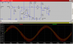
Here's for example what happens with the earlier posted TMC sim if the load is changed to 100nF in series with 4 ohms (looks like a typical Zobel network!) and the bias of the output stage reduced by changing the 495 ohm resistor to 2000 ohms. The input signal is 5 kHz 10 mV pk sinewave and the amplifier oscillates at about 200 kHz.
It doesn't look dangerous neither for the amplifier nor the speaker though with such a low amplitude.
It doesn't look dangerous neither for the amplifier nor the speaker though with such a low amplitude.
Attachments
- Home
- Amplifiers
- Solid State
- Bob Cordell's Power amplifier book