It's not an F5, but JimT's cascoded BA-2, drives 6 pairs of devices at around 50v.
If you have inefficient speaks, or big 15" drivers, think about that.
Well it's not the same as an F5 so it might not work.
It would be nice to know the limits of the F5 circuit - what is possible and what isnt.
I haven't read yet the whole thread yet (I'm still by post 2.000), but wondering, has anybody already made a point to point build with this design?
I have removed the protection and the the thermal compensation, and it leaves a total count of 20 components per channel. Assuming soldering about 10 components on each mosfet's (legs), it seems pretty easy to me")
Even easier if 6 power resistors are TO220.
Have to think a good position for the pot, for it to be easy to be trimmmed.
Any ideas or previous attempts?
Regards,
Regi
I have removed the protection and the the thermal compensation, and it leaves a total count of 20 components per channel. Assuming soldering about 10 components on each mosfet's (legs), it seems pretty easy to me
Even easier if 6 power resistors are TO220.
Have to think a good position for the pot, for it to be easy to be trimmmed.
Any ideas or previous attempts?
Regards,
Regi
How many output pairs can the input JFETS realistically drive?
Is 2 pairs the maximum, or 3 or 4?
I haven't read yet the whole thread yet (I'm still by post 2.000), but wondering, has anybody already made a point to point build with this design?
Any ideas or previous attempts?
Regards,
Regi
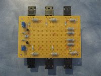
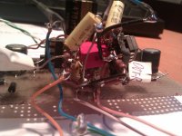
I built this sucker up ages ago. It is point to point on proto board with 3 pairs at the output.
It has been tested in the lab and been found to be completely stable under resistive and reactive loads.
It also sounds quite nice
Thank you Prof Pass
I got a chance while the wife was out to have listening sesion.
Three pair output version I built up ages ago.
I had a chance to listen to Sting.
Attachments
Last edited:
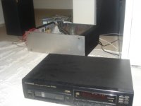
Looks fine, but I mean authentic point to point, no boards messing around.
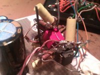
Attached is a (really integrated) preamp I made with OPA2134. There's a board for the big caps and the PSU, but it is there mainly for holding the ball of soldered components. With an F5 that is not needed because of the mosfets attached to the HS holding all the stuff.
Guess how does it sound
Edit: In fact, it is a two stage preamp composed of 3x-gain-stage - pot - buffer
Attachments
Last edited:

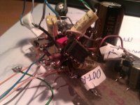
....thinking about the grounding arrangement...
thats the funny thing.....is there any
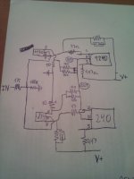
I have just drawn how the components would be layed down. More or less. Now take this image and try to tridimensionalize it, make the leads shorter and....thinking about the grounding arrangement...
Damn! not another F5! I've just built one
You'd gain from thermally coupling the K170 and the J74 maybe
I built this sucker up ages ago. It is point to point on proto board with 3 pairs at the output.
It has been tested in the lab and been found to be completely stable under resistive and reactive loads.
It also sounds quite nice
Are all the other board components standard, or were there required changes for this increase in output devices?
Russellc
It's not an F5, but JimT's cascoded BA-2, drives 6 pairs of devices at around 50v.
If you have inefficient speaks, or big 15" drivers, think about that.
Is there a thread on this build? What all had to be changed to run it like this? (The BA-2) I have searched for member "JimT" but am not getting any results?
Russellc
Last edited:
Is there by chance anyone that has an Eagle lrb file containing all the fets and the zetex devices used in the F5?
Working on a schematic for a cascoded 4 pair output and Eagle is hard enough using as it is, creating parts myself would be too much.
Google doesnt seem willing to be helpful today.
I am used to using Mentor graphics PADS Logic and PADS Layout at work, in many ways it is just soo much easier. But considering the cost Eagle doesnt seem half bad. Although having to learn how to use a new program is a real pita. Once you get used to doing things a certain way you can easily get annoyed when the new program doesnt do things like you are used to.
Oh and at work we have a guy who is responsible for creating components, spares me the headache.
Last edited:
Sorry, I didn't read that post, my apologizes.I think I would mount a micro fan in a tube, blowing directly on the devices, inside
with ordinary heatsink ribbing, I dont see a fan being very optimal
its disturbing the natural convection flow
I reckon there would quite some gain from lowering temperature inside the box
Based on my long term experience with silent PCs, I don't agree with that. Natural convection is nice as long as you don't have anything better.
Just put it in perspective with a new CPU processor. They are designed to produce 130W per device at full working load. Compare it to the nearly 62W that an F5 channel burns.
Then we can conclude that with forced airflow we can manage large amounts of heat in a very reduced space (Core i7 heatsink).
To make it more silent, increase both heatsink and fan size.
Regards,
Regi
creating parts myself would be too much.
Yes it's a lot of work to create your own part library, but, believe me, it really pays off. So far every library I downloaded somewhere had issues.
See it like this - it's just a few parts, copy & paste will reduce the job further
Are all the other board components standard, or were there required changes for this increase in output devices?
Russellc
All the values were kept the same.
However I left out current limiting circuit and biasing thermistors.
All the values were kept the same.
However I left out current limiting circuit and biasing thermistors.
Excellent! I had no idea the circuit would drive that many outputs as is. Bias or other supply differences I suppose? Higher voltage rails? Larger heat sinks?
I'm getting ready to buy some more heatsinks, more F-5 amps need built, this sounds very interesting.
Russellc
About leaving out those Thermistors .....
When you leave out the temp compensation Thermo (and it's 2k2R resistor), you have to screw the pot down further (reduce it's resistance) to compensate and it's no problem, but ....
- this puts more current thru the small wiper of the pot (usually cermet if it's a multiturn one), and there is a limit to how many mA you can pass thru this for both long life and without deteriorating the sound of the cermet pot (even further- IMO)
For example, with the TH1 in cct and at 25*C, you have the resistor at 2.2kR in // to the TH1+2k2 at 6k7R in // to the pot, that will be about 1kR (to give sum total R about 600R if 7mA jfets used) and this sends 4.2mA thru the pot (if my sums are okay).
When the TH heats up to about 60*C (50*C on sink), we have the same 1.9mA thru the 2k2R resistor, the 6k7R drops to about 3k6R (1k4R + it's 2k2R) and pot is then set to about 1.1kR (= about 3.8mA) which is it's final temp stable operating point
Removing that TH (and it's resistor) means the pot has be reduced to about 850R in // to just the 2k2R resistor to sum to the same 600R, so the current thru the pot now goes up to about 5mA - it is quite a lot!
Now, as 5 of the 7mA thru this composite "gain resistor" goes thru the trimpots (cermets are not known for sonic excellence), this is a significant limitation to the overall sound quality of the amp - it is better than the original scheme, mind you (27% thru resistor, 56% thru pot + 17% thru TH) - the sound contribution via those thermistors is 'not very' good at all!
'qusp' told me about the very good Vishay Zfoil pots that are quite expensive but obviously do sound pretty good (!) - they also, unfortunately, have max wiper current limit of 3mA, so even with these as pots for better sound, we still need to consider changing some of those resistor values.
It's pretty straight forward - To initially get the low o/p dc offset, the pots are used, then replaced with equivalent resistors after temp & component settling period - those 'cutdown' IC sockets work quite well, and just plug the components in.
No pots, no THs, no ZTXs - it all sounds better, and the really good quality resistors are worth the extra $s and effort.
One thing, the fets DO need to be HOT for best sound - 50*C+ for the heatsinks (= 60*C+ fets) - a lot of these amps are built to run just warm - need to be quite HOT
Also, diodes (esp Shottkys) are just the opposite, cold as possible.
........ so the current thru the pot now goes up to about 5mA - it is quite a lot!
interesting evaluation
and complicated
those trim pots are rated at 0.5watt, and the longer ones maybe more
why would 5ma be a problem ?- Home
- Amplifiers
- Pass Labs
- F5 power amplifier