I can't possibly guess at a system that I can't experience and also take measurements as a whole. The reg lowers its Zo with more standing current spared to it up to a point. That is one thing. Interactions and subjective preferences with an unknown to the reader valve circuit that it serves its another. Set it wherever you think its more likeable to you as long as it stays in good working order.
Ok will do thanks.
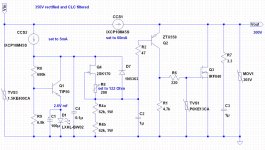
Why don't you just lift Vbe with a bypassed resistor if engulfing the FET in higher VDS is your goal, and keep a single common CCS? That example in the pic could give you 7-8V for instance. Saves you a great deal of headaches and its lower parts count.
Have tried your suggestion and have also used low impedance capacitor as you suggested. Here is my observation: Vout took forever to stabilize after energization; ripple content worsen under actual dynamic loading condition; the Aikido pre-amp that being fed by this reg setup sounded very lay back and unusually slow. Basically the reg seem imposted too much of its own character onto the load (the Aikido pre-amp), interesting. This is not my first time using Aikido pre-amp, by the way.
Because of that I reverted to my previous circuit setup but with additional enhancement as shown in the attachment. The result was a very satisfactory one. I didn't know how the original design sounded like as I didn't have the necessary parts to build one but this one is good enough for me. At least, I don't need to worry about any power component may fail on me for no apparent reason as the CCS is fully rated and the gate of Q3 is protected. I bet the original design would have sounded even better given sheer amount of compliment and positive reviews posted in this thread.
Thanks again for your inspiration and comments all along, Salas.
Attachments
How to setup Salas regulator
Hi,
I am going to build Salas HV regulator. How do you adjust current for regulator? I mean if R1 is 56 Ohm, then current draw is cca 40mA. Is this total current with load or just for regulator? If just for regulator how high should be this current? - twice the expected load?
Thank you.
Hi,
I am going to build Salas HV regulator. How do you adjust current for regulator? I mean if R1 is 56 Ohm, then current draw is cca 40mA. Is this total current with load or just for regulator? If just for regulator how high should be this current? - twice the expected load?
Thank you.
Have tried your suggestion and have also used low impedance capacitor as you suggested. Here is my observation: Vout took forever to stabilize after energization; ripple content worsen under actual dynamic loading condition; the Aikido pre-amp that being fed by this reg setup sounded very lay back and unusually slow. Basically the reg seem imposted too much of its own character onto the load (the Aikido pre-amp), interesting. This is not my first time using Aikido pre-amp, by the way.
Because of that I reverted to my previous circuit setup but with additional enhancement as shown in the attachment. The result was a very satisfactory one. I didn't know how the original design sounded like as I didn't have the necessary parts to build one but this one is good enough for me. At least, I don't need to worry about any power component may fail on me for no apparent reason as the CCS is fully rated and the gate of Q3 is protected. I bet the original design would have sounded even better given sheer amount of compliment and positive reviews posted in this thread.
Thanks again for your inspiration and comments all along, Salas.
Since that experiment with the capacitor and resistor lift you examined worsened the results, obviously you did well to revert to your double CCS version. I keep the result of the Vbe lift as a no good option, not to be considered for changing the standard design. Thanks for the feedback. Enjoy your system, since its nicely sounding & steady with your reg as it is configured.
And how much current should be left just for regulator?
20-25mA is good enough to be spared in the regulator.
20-25mA is good enough to be spared in the regulator.
For both high volatge and low voltage versions?
Since that experiment with the capacitor and resistor lift you examined worsened the results, obviously you did well to revert to your double CCS version. I keep the result of the Vbe lift as a no good option, not to be considered for changing the standard design. Thanks for the feedback. Enjoy your system, since its nicely sounding & steady with your reg as it is configured.
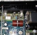
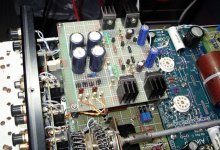
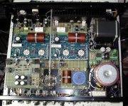
Attached is the result of the whole project. The one on the left is the HV Shunt Reg, and the middle one is the Bipolar LV Shunt Reg.
Attachments
Hm, interesting project. Is this just aikido preamp?
I am planing using HV shunt regulator also with aikido. What are your observations about sound quality you gained with aikido?
Very good, sound better than you think! I believe this!
Attached is the result of the whole project. The one on the left is the HV Shunt Reg, and the middle one is the Bipolar LV Shunt Reg.
A busy but orderly construction. Nice.
Salas,
I have a question. I want to build a Dynaco Mark IV. This amp needs a 740 volt high voltage supply and a 55 volt bias supply. I have some large vintage transformers that have 794 volts output. Both these transformers and the Mark IV's used tube rectification. Which is less efficient that solid state. I could buy another transformer for the bias supply. But my question is, is it possible to build a regulator that would have the 794 v input and both a 740 and 55 volt outputs?
I have a question. I want to build a Dynaco Mark IV. This amp needs a 740 volt high voltage supply and a 55 volt bias supply. I have some large vintage transformers that have 794 volts output. Both these transformers and the Mark IV's used tube rectification. Which is less efficient that solid state. I could buy another transformer for the bias supply. But my question is, is it possible to build a regulator that would have the 794 v input and both a 740 and 55 volt outputs?
Mr2racer-
740v is unusually high. Perhaps you are measuring the the full voltage across the B+ windings. MkIV's (& most tube amps) use full wave rectification, which would be ~ half that.
MkIV manual-
http://www.the-planet.org/dynaco/Amplifier/Mark IV.pdf
You need ~435vdc and a lot more current than the Salas HV shunt was designed for.
It is not practical to apply shunt regulator for tube output stage.
I think it would be possible to use the SSHV for a 45 SET, it will be a headphone amp though. I'm going to try it eventually. May even use an SSHV on the cathode to provide 130+V's to DC couple to the gain stage and forgo a bypass cap. These things open up a lot of possibilities.
- Home
- Amplifiers
- Power Supplies
- Simplistic MosFET HV Shunt Regs