Don't worry, it's coming: Parts-Express.com ? CBT36 Line Array Speaker System
Should be most interesting to see.
Dan
Should be most interesting to see.
Dan
That's funny! Those look like Don's speakers for sure.
I guess P.E. found a bunch of small, cheap drivers for the tweeters. Looking forward to seeing the kit.
The hardest part of building it has to be all the holes and routing. Don had a bare front panel there. It was all done by CNC.
I guess P.E. found a bunch of small, cheap drivers for the tweeters. Looking forward to seeing the kit.
The hardest part of building it has to be all the holes and routing. Don had a bare front panel there. It was all done by CNC.
Yea, I believe the kits will be cnc'ed, but I don't know. If not, the woodworking would be beyond me. Can't wait to see some people build these though. I really like the concept.
Anyone want to take a stab at what the price will be? I'm betting more than I want to spend, but hopefully not more than I will spend. $2-4 grand seems to be what the PE TTers are saying. OUCH!
With a 1kHz crossover and possibly <3" c-c spacing, the horizontal lobe should be broad. Makes me like the concept.
Dan


$700 plus for drivers and then add in the crossover parts and the cabinets, multiply it by 2 and you've got a chunk of change.
Being that it's 5ft tall will pretty much eliminate it as a center channel in my HT. Maybe they'll have a second 3 ft tall version. For the 2 channel loyalists, HT surrounds, or mono aficionados it should make for a very cool speaker.
Anyone clearly understand what differentiates it from a line array and can state it simply? I just don't get it.
Thanks,
Dan
Anyone clearly understand what differentiates it from a line array and can state it simply? I just don't get it.
Thanks,
Dan
Yep, the curve and shading.
An infinite line array has the ideal performance that we want: no variation with listener's vertical position. Chop it short to a practical length and it has lobes and height dependent frequency response. Tapering off the response between the middle and the ends can improve the lobing and response variation (called shading, see reference to a paper I wrote on that, a few pages back).
Don found an even better approach with level tapering and time delay for the units towards the ends of the line. The curvature is just a practical way to create the time delay (It isn't about firing energy upwards!).
David
I'm glad PE is doing this, especially if they take care of milling the baffle. Maybe a flat pack with the other boards, too?
I probably won't be putting a pair in my home, but I would like to build one channel and try it for a mobile mono PA. I have a friend who just went pro singing solo gospel. He does a lot of small and medium churches, and one of these CBT arrays on the stage floor behind him might make a nice portable PA speaker. He doesn't usually go terribly loud... Think one of these could fill a church sanctuary?
It may be kinda pricey for home stereo, but if it can do decent SPL, it might be quite a value in PA.
Last edited:
I was thinking of just building a center channel first using what Don used.
Dayton ND90-8 3-1/2" Aluminum Cone Full-Range Driver 8 Ohm | Parts-Express.com
I cant find the tweeter that Don was saying he used though.
And my biggest question is how do I decide what arc to use for my room?
Dayton ND90-8 3-1/2" Aluminum Cone Full-Range Driver 8 Ohm | Parts-Express.com
I cant find the tweeter that Don was saying he used though.
And my biggest question is how do I decide what arc to use for my room?
Last night I went to a lecture by Paul Bauman of JBL on the Vertec series of line array systems. He spoke for over 3 hours on pro-sound line arrays, their theory, and a lot of the recent big installations.
This is very similar to CBT with large curved arrays and shaded drive to create desired audience coverage. The software is extremely sophisticated. You can lay out an audience seating area with main floor and multiple balconies and play with the array positioning, delay and drive to get absolutely constant level at every seat, even though there may be a 4 to 1 or greater distance variance between front and back locations. Think of CBT as the precooked version of this and Vertec as make-your-own with stackable array modules.
Main left and right stacks might be augmented with flanking systems, delayed systems mid field, and center stage fill in speakers. EASE software would then plot out level over the whole stadium, football field, etc.
Not exactly home hifi stuff, but it indicates the capability of line arrays.
David S.
Late to the discussion here, but I just wanted to check something Audiopioneer said back in post 51:
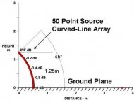
Is this in fact how DBK's demonstration array is shaded? Because that seems quite different from the model in his paper, which has labels of -0 dB, -0.8 dB, -3.4 dB and -9.2dB and -Inf dB.
the top drivers are at -12dB, the shading occurs in steps of 0, -3, -6, -9, -12dB with a net loss of just under 3dB for the array.
Is this in fact how DBK's demonstration array is shaded? Because that seems quite different from the model in his paper, which has labels of -0 dB, -0.8 dB, -3.4 dB and -9.2dB and -Inf dB.
Attachments
Can anyone describe exactly how the shading is accomplished in the real-life demonstration model? I didn't see any nuts-n-bolts discussion in a quick survey of this thread and accompanying links... Are groups of multiple drivers operated at the same level, for a stair-step power tapering effect, or is each driver individually padded?
Last edited:
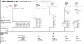
Shading is combination of driver wiring and resistors, depending on the shading group. Each driver is not shaded, but the shading is done in steps/groups. See slides 50-53 in Keele's CBT presentation.
Attachments
Thanks Thune.
Hmm. So 5 driver groups with stepped shading. In Keele's paper, my take was that he was using an idealized simulation with individual driver shading. (Please correct me if I'm wrong.) If so, I'd like to see a simulation of the real-world stepped shading to see how results diverge from the idealized version.
Or maybe, as with so much else in audio, the ear really isn't as sensitive to measured differences as our pride would have us believe?
Edit:
I just remembered he has actual measurements of a prototype toward the end of the paper. I assume that's the step-shaded implementation?
Last edited:
- Home
- Loudspeakers
- Multi-Way
- Constant Beam Width Transducers line arrays