I'm trying to post as much information as possible in the first few pages...
Some parts in the Goldmund Mimesis 3 amplifier vary from amp to amp:
R1 varies like this: 1K, 1.2K, 1.5K
R2 varies like this: 20K, 51K, 100K
C1 varies like this: 100pF, 120pF, 150pF
C2 varies like this: 4.7pF, 10pF
NOTE: The output MOSFETS must be matched!!!!!!!!
Some parts in the Goldmund Mimesis 3 amplifier vary from amp to amp:
R1 varies like this: 1K, 1.2K, 1.5K
R2 varies like this: 20K, 51K, 100K
C1 varies like this: 100pF, 120pF, 150pF
C2 varies like this: 4.7pF, 10pF
NOTE: The output MOSFETS must be matched!!!!!!!!
Last edited:
Hello
Nice project.
Both the model 9.2 and model 3 use phase lead capacitors. In the model 3 it's C3 and maby C4, using those cap allow to use much lower value for the VAS cdom cap (C2) and the VAS are not the usual type. Using phase lead capacitors give a better sound.
Bye
Gaetan
Nice project.
Both the model 9.2 and model 3 use phase lead capacitors. In the model 3 it's C3 and maby C4, using those cap allow to use much lower value for the VAS cdom cap (C2) and the VAS are not the usual type. Using phase lead capacitors give a better sound.
Bye
Gaetan
I'm trying to post as much information as possible in the first few pages...
Some parts in the Goldmund Mimesis 3 amplifier vary from amp to amp:
R1 varies like this: 1K, 1.2K, 1.5K
R2 varies like this: 20K, 51K, 100K
C1 varies like this: 100pF, 120pF, 150pF
C2 varies like this: 4.7pF, 10pF
NOTE: The output MOSFETS must be matched!!!!!!!!
Or if not possible, use source resistors
")
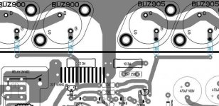
Updated Goldmund Mimesis 3 schematic to show more detail/info:
An externally hosted image should be here but it was not working when we last tested it.
3.) I will order a pair of the PCB boards from a high quality US manufacturer. The order will be placed the following Monday after Thanksgiving Day.
4.) I will build this amplifier step by step on this thread, with pictures and explanations. The PCB boards will be tested for quality, functionality, fit of parts, etc. The final amplifier will be tested on a Tektronix.
What do you think the realistic time frame will be before we see the boards and the start of the build?
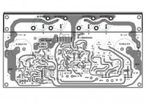
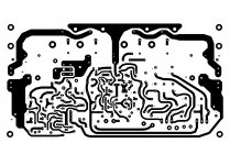
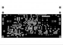
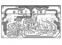
Here is the layout that will go to the PCB manufacturer either next week, or the Monday after Thanksgiving Day. All PCB layout questions and suggestions are welcomed. All comments directed at making changes to the schematic will be ignored, unless of course there's a mistake somewhere
Attachments
There's room to spread the output transistors a bit farther apart--that might help to dissipate heat.
Source resistors are probably a good idea if this is to be used by many with varying levels of expertise---not everyone has the ability or the tools to match the outputs perfectly (and it would necessitate buying several extra outputs to find good matches). Those that are confident they can match to a very high level can put a wire link instead of the resistors.
Source resistors are probably a good idea if this is to be used by many with varying levels of expertise---not everyone has the ability or the tools to match the outputs perfectly (and it would necessitate buying several extra outputs to find good matches). Those that are confident they can match to a very high level can put a wire link instead of the resistors.
I agree with spreading the mosfets further apart. Although it is definitely not a show stopper.
One way around the matching issue is, if people are still interested to build this and can agree on buz series or exicon parts etc. Then a group buy could be placed and someone with the instrumentation and experience could match them on behalf of the group, and post them out to the relevant people.
One way around the matching issue is, if people are still interested to build this and can agree on buz series or exicon parts etc. Then a group buy could be placed and someone with the instrumentation and experience could match them on behalf of the group, and post them out to the relevant people.
Last edited:
Spind - Again, the source resistors can be installed between the bolts of the MOSFETS. There's no need to change anything on the PCB.
Those who can't afford to buy a few extra sets of MOSFETS, or know how to properly match them, should really not be building this amplifier.
As for spreading the MOSFETS further apart, I disagree. The closer they are, the better the heat dissipation will be through the heatsink. They will also sound better.
Last edited:
what?As for spreading the MOSFETS further apart, I disagree. The closer they are, the better the heat dissipation will be through the heatsink.
Hi Nagys
I think it would be good to have some ground-plane continuity between the left and right side at the top of the PCB near the Mosfets, to have a low impedance path between the "earthy" ends of the 1uF decoupling caps and zobel.
This can be done by moving the tracks between the drivers and gate stopper resistors to the other side of the PCB and moving the zobel components down a bit. See pics below.
It may also be a good idea to put the 1uF decoupling caps closer to the Mosfets. To do this you'd need to have the power rails come out from under the heatsink bracket close to the Mosfets.
Cheers - Godfrey
Attachments
The transistors should be mounted as close as possible to each other and in the center of the heatsink. The more uniform the heat, the better the sound. End of story.
Really? How so?
Tekko - For those who would like to use source resistors, they can be installed between the bolts of the MOSFETS. There's nothing to change on the PCB.
Naggys I dont know why you are so staunch about this. You have stated that the must be matched for this build. Some people will build this amp with parts on hand and may not be matched. I dont know if its possible to buy these matched anyway. If you allow space for the source transistors then if in teh unlikely event you have matched fets you can just use a jumper wire. Why all the fuss over these resistors?
Godfrey - I made some changes according to your suggestions. I'm going to leave the 1uF/100V capacitors where they are... The temperature near the MOSFEST will be high and it's better if these caps are slightly positioned away from the transistors.
Attachments
Luke - I can ask you the same question: Why all the fuss over these resistors?
I will also repeat this for the 3rd time: Individuals who would like to use the source resistors can install them between the two MOSFETS' mounting bolts. This is actually the easiest way to install them if using TO3 transistors and the proper way. No changes need to be made to the PCB. Therefore, I obviously cannot take these requests.
1.) Cut the resistor's leads to correct length.
2.) Solder a ring terminal on each end of the resistor.
3.) Take the nuts off from the bottom of the PCB, the ones that hold the MOSFET in place.
4.) Take the lock washers off.
5.) Install the resistor by putting the ring terminals around each of the two bolts.
6.) Put the lock washers back on.
7.) Put the nuts back on and tighten them.
8.) Repeat for all four MOSFETS, or eight if it's a stereo amplifier.
And now the amplifier will have source resistors. Is everyone happy? Or do we need another thirty posts regarding this?
Luke - I can ask you the same question: Why all the fuss over these resistors?
I will also repeat this for the 3rd time: Individuals who would like to use the source resistors can install them between the two MOSFETS' mounting bolts. This is actually the easiest way to install them if using TO3 transistors and the proper way. No changes need to be made to the PCB. Therefore, I obviously cannot take these requests.
1.) Cut the resistor's leads to correct length.
2.) Solder a ring terminal on each end of the resistor.
3.) Take the nuts off from the bottom of the PCB, the ones that hold the MOSFET in place.
4.) Take the lock washers off.
5.) Install the resistor by putting the ring terminals around each of the two bolts.
6.) Put the lock washers back on.
7.) Put the nuts back on and tighten them.
8.) Repeat for all four MOSFETS, or eight if it's a stereo amplifier.
And now the amplifier will have source resistors. Is everyone happy? Or do we need another thirty posts regarding this?
Your question has an obvious answer. If most people build it with unmatched fets then they should use resistors, therefore there should be a place on the board. Its tidier, what your proposing is more work and its butch. I see absolutely no advantage in not having a location for these.
This is a community of geeks all with an opinion as you've no doubt noticed
Why not take a vote. If the majority agrees with your approach then Ill stop talking about it. Promise- Status
- Not open for further replies.
- Home
- Amplifiers
- Solid State
- Goldmund Mimesis 3 Clone, World's Best Amplifier!!!!