Rudi, the issue is safety not function. In your picture above, the trace that the "mm" of your dimension falls on is a low voltage trace. There really isn't a reason for it to be so big since it doesn't carry a lot of current. Reduce its width to allow more space between it and the mains connection. I'd grind a bite out of it on your current board.
I agree. The distance is very small. This board is simply dangerous. On my soft start board I keep at least 10mm distance between the mains, and the low voltage tracks.
Sajti
This is working perfect over the years in many amps of mine.")
Very nice. I use similar approach, but I use 12V for tube filament, so power relay from it.
Originally posted by samsagaz
some IC that help me to that?
Check out the MOC3041
Hello Andrew, John,
I am happy to tell you, that my smal "Soft-Power-On" - board "works as designed".
Best regards - Rudi_Ratlos
P.S. Andrew: the picture's size is 86 KB. Is it s till too big?
I am happy to tell you, that my smal "Soft-Power-On" - board "works as designed".
An externally hosted image should be here but it was not working when we last tested it.
Best regards - Rudi_Ratlos
P.S. Andrew: the picture's size is 86 KB. Is it s till too big?
Hello Andrew, John,
I am happy to tell you, that my smal "Soft-Power-On" - board "works as designed".
Good to hear! It looks good too.
On the subject, here is what I use:

It runs from the + rail of the supply it is limiting, so no extra transformer needed:

Works well.
I think D2 may be redundant, D1 will clamp spikes in both directions.
I think moving the anode of D2 to the base of Q1 would be worthwhile. After you move the anode of D3 to the AC side of the main rectifier it will cause the charge on C1 to bleed off as soon as power is removed, even for a moment, and give a fresh timing interval. Make the diodes 1N4004 (or higher voltage).
Consider using a higher coil voltage on the relay.
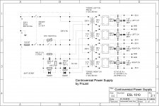
What do you think of this one:
TOROIDAL TRANSFORERS - Soft Start
I use 2 of them, 1 in my monoblocks 2000VA.
Is this a good design?
Rudy
TOROIDAL TRANSFORERS - Soft Start
I use 2 of them, 1 in my monoblocks 2000VA.
Is this a good design?
Rudy
Hello Andrew, John,
I am happy to tell you, that my smal "Soft-Power-On" - board "works as designed".
An externally hosted image should be here but it was not working when we last tested it.
Best regards - Rudi_Ratlos
P.S. Andrew: the picture's size is 86 KB. Is it s till too big?
Rudi, I'm glad it works, not that there was much doubt. Did you grind away some of the low voltage ground trace to get >6mm between it and the mains traces? This suggestion is for your safety.
wich are the RULES about minimun distance of High and Low Voltage traces?
What about recommended size?
One more question. if i made an toroidal tranformer 25-0-25 to the PSU and in the same toroidal have 12V secundary, this will be the same that if i have 2 tranformers? or maybe will introduce some noise?
Thank in advance
What about recommended size?
One more question. if i made an toroidal tranformer 25-0-25 to the PSU and in the same toroidal have 12V secundary, this will be the same that if i have 2 tranformers? or maybe will introduce some noise?
Thank in advance
What do you think of this one:
TOROIDAL TRANSFORERS - Soft Start
I use 2 of them, 1 in my monoblocks 2000VA.
Is this a good design?
Rudy
This exact schematics, simple but effective, was originally published in Elektor Electronic a long time ago ... and just like allways, without any authorization, there's someone making the business out of it. Otherwise this is simple relay delay (fixed delay time) made out of passive components and thus very reliable.
This exact schematics, simple but effective,
...is off-line powered.
The best location for a slow charge circuit is in the secondary between the transformer and the capacitor bank. Again the slow charge NTC or resistors need to be bypassed when the caps are near full charge.
Any technical justification for this assertion?
I can think of two reasons why it is not the case.
The secondary of a psu can have many different voltages requiring special control devices. ( try and soft charge a 4kv supply with secondary side controls)
The inrush current will need to be limited by a separate circuit.
Arguments for mains side current limiting:
Standard components can be used, mains coil voltage relays can be obtained in any current desired. mains voltage timers if required are readily available.
The starting system only needs to take into account the Joule rating of the capacitor bank, any load on the psu at start up and the characteristics of the supply.
Secondary voltage is immaterial.
Inrush current limiting is provided by the same components thereby reducing component count and possible interactions.
On a valve amp with heaters powered off the main transformer the heaters get a bit of a soft start as well.
The only technical problem I can see is if some the the main transformer's loads require power before the main DC supply comes on line there might be a problem. Larger designs often power up any control voltages from a separate transformer which is powered up first.
Regarding to address of this topic, mine is still cheaper and easier to built of them all. It also energize the relay at just the right time, every time.
I can trump that
One resistor and one relay (AC coil) and no need to adjust anything if more filter capacitors are added. put the resistor in series with the primary of the transformer use the NO relay contacts to short out the resistor. Wire the coil of the relay across any power transformer winding of suitable voltage, I usually use the primary or a 24V winding because relays of these voltages are common.
Size the resistor for an inrush of 4 - 5x FLA (full load amps).
- Status
- This old topic is closed. If you want to reopen this topic, contact a moderator using the "Report Post" button.
- Home
- Amplifiers
- Solid State
- Cheap and Easy Soft Start?