if 1meg then you can probably get away with 0.1uf for a corner of 1.591549433hz and IMD up to 15.91549433hz this is for output cap, owen can probably help more with the input as I dont use it, neither does he AFAIK
My problem is that I doubt if the stepped attenuator type shunt don't affect the 1Meg input impedance of Borbely Line amp because each step of the attenuator is changing the impedance....
oh in that case, I would think it will, in fact it will probably dominate, so the output caps should be sized to account for bass all the way down at the minimum input impedance of the attenuator. this problem is not specific to this IV, the information you seek should be covered in the attenuator manual. find out what the minimum apparent input impedance is and calculate for that
Hi Guys,
Gogu:
Sorry about that, I have no idea why I thought your board was going to qusp. I'll correct the list, and your board will ship to your proper address this evening.
I have the following three boards being shipped to qusp tonight:
1. flocchini
2. jameshillj
3. qusp
Please correct me ASAP if this is wrong. I'll be shipping them tonight, and once they're gone, they're gone...
Horio:
Thanks for the payment! Your board will be going out tonight as well.
Nikon1975:
I sent you a PM with your total.
Did anyone else have any address changes? I really hope not, because everything shipped the the listed Paypal addresses. I have over 250 emails in my inbox relating to this group buy, so it's extremely difficult to keep track of shipping requests other than what is directly in the Paypal shipping instructions.
Please let me know about any issues as soon as possible.
Regards,
Owen
all good Owen, even if we are both mistaken, hes just up the road anyway so its no drama.
Merlin yep sounds like a plan, 2.2 would be really pushing it IMO, but perhaps 4.7 would do in a pinch and you wouldnt notice the IMD in the audio band. personally I would go for at least 6.8, with 8 being preferred, just to cover all bases
Merlin yep sounds like a plan, 2.2 would be really pushing it IMO, but perhaps 4.7 would do in a pinch and you wouldnt notice the IMD in the audio band. personally I would go for at least 6.8, with 8 being preferred, just to cover all bases
")
Hi Guys,
Whew... what a week. Pretty much everything that can go out, has gone out. I've updated the list yet again with ship dates, and there are only a few more boards left to ship.
I want to extend a big thanks to everyone for their patience... I know this all took much longer than planned. I also want to thank those on the waiting list for stepping up and taking the boards for those who dropped out. From the looks of it so far, I don't think I'll be left with any unplanned extras, which is a big weight off my shoulders.
I have sent emails out to richluvsound and TheShaman to see if they'll take the last two extras, and if so, then every board will have been sold.
Check out the list, and let me know if there are any issues.
Cheers,
Owen
Attachments
Hi Guys,
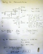
I decided to post the transconductance measurement method on here so everyone could use it if need be.
I've attached a drawing that shows the circuit used, and the calculation.
It's not exactly quick, but a good power supply (one that doesn't fluctuate),a good signal generator and three DMM's will make things much easier.
You'll need the following to do this correctly:
1 Lab PSU set to 45VDC
1 Breadboard
1 DMM (two is better, three would be best)
1 Signal Generator set to 1kHz
Hook up the circuit as shown, and hook one DMM across the 200R, one across gate to source, and one from the wiper on the pot to ground. If you only have one DMM, you'll have to keep moving it around.
Set the DC operating point for the fet by disconnecting the signal generator and adjusting VR1 to get 24VDC across R1. At this point, you'll have 120mA Id and 21VDS which is very close to what the fet will see in the actual circuit.
Let it stabilize and adjust as needed to get as close as possible to 21VDC across R1. Measure the voltage at the wiper of the pot, and write it down. This will be your measurement for VDS matching. If you adjust each fet to the same 21VDC across R1, then you know that VDS will be the same, and the DC voltage on the gate (measured from the wiper on the pot and NOT the actual gate) will be the voltage value that gives you the set VDS for that fet. If two fets have the same voltage on the gate to get same VDS, then they are matched.
Once you have the VDS matching done, connect the signal generator through an AC coupling cap and adjust the output to get 3VRMS across R1. Once you have 3VRMS, measure the AC voltage from gate to source (VGS) and write it down.
If you're doing a lot of fets, you'll want a way to number each fet , and then make an Excel spreadsheet that will calculate Gm from the numbers you measure, namely VGS and VR1. You'll also want a quick way to mount each fet to a heatsink. I used a screw and a spring clip with a hunk of aluminum. The 200R resistor will also need a heatsink, and you'll probably want to mount everything on a breadboard to make it easy to swap fets in and out.
With a large enough number of fets, it will be easy to find pairs that have very close VDS values as well as Gm. It took me 2 hours to measure 14 devices and I found four that were very closely matched. I was using 3 Fluke DMM's and all the right lab equipment, which really helped to speed up the process.
As you can see, this whole process is VERY time consuming, and a serious PITA. All these values a temperature dependent, so each fet needs time to reach equilibrium. Please reward qusp accordingly for the time he puts into this. If I were doing it, I'd be charging a pretty penny for each matched pair.
Let me know if there are any questions or issues.
Cheers,
Owen
Attachments
hmm I dont have an actual tone generator, but I have lots of pro audio software and a RME pro audio card capable of 32/192khz balanced output. shouldnt be hard to produce a 1khz square wave (assuming it should be square) then can use a simple opamp circuit to allow amplification to give 3vac. sound like a plan OPC? or should I search for a used old tone generator?
@qusp
Legato is a good contender, standard kit with no mods & no new parts sounds very good with B II....far better than IVY
yeah I thought about trying it out just for kicks, but I would end up blowing too much on nice caps for it, plus there are better options for IV of this type IMO, just build the borbely IV/line amp from the audio express artical and acko's upcoming jfet IV looks great, if I were pursuing the buff for home I would probably give it a try, but I think this here circuit we are discussing is superior anyway.
Merlin let us know how it sounds with various "boutique" caps you might try. I was thinking AmpOhm.
yeah the ampohm copper and polypropylene is quite nice. best medium budget combo would be a large polypropylene bypassed with small teflon. thats what i'll be doing, havent fully decided on the large cap, but bypasses will be vcap CuTF copper teflon. already have 2, just need another couple. my amp has 1mo inputZ, so I can probably forgo the large cap altoghether, but I want to maintain compatibility with variety of amps
I'm thinking about mounting caps and resistors (the one after the caps in the circuit) on the XLR so that I can change and compare the different IV boards.
May try the .1 Russian teflons as a bypass.
Thoughts
Thanks
FT-3 is the better but are bigs.
- Status
- This old topic is closed. If you want to reopen this topic, contact a moderator using the "Report Post" button.
- Home
- Source & Line
- Digital Line Level
- A New Take on the Classic Pass Labs D1 with an ESS Dac