If I reduce the unloaded voltage by .01v, it halves the result.
324mOhm with DVM readings. Tiny things show it enough times up or down easily. Would it drop double 0.02V if it is a 150R for instance? Was the Vref well steady? Just keep it held well. Was there remote sensing to the 330R by the way?
324mOhm with DVM readings. Tiny things show it enough times up or down easily. Would it drop double 0.02V if it is a 150R for instance? Was the Vref well steady? Just keep it held well. Was there remote sensing to the 330R by the way?
Salas,
I will try with 200r and 150r, I will also try with double voltage. The Vref was steady, used aligator clips to hold the test leads. Remote sensing was used.
Salas,
For my application, I would like to get about 60v out of the regulator, maybe I'm stretching it a bit too much, but, thought I would give it a try. What's the worst that can happen, smoke?
I tried jumping the voltage, but, it's a bit high going in at approx 70v. I looked at the simulation and saw that Q3 would be over it's ratings for Vcbo and Vceo, so I put a 2sc3503E in it's place. This is for the positive regulator. The regulator fires up and runs, though the voltage creeps up 10mv every two or three seconds. I've set it at 60v out and put 1k load resistor on it. The load resistor is a 5 watt resistor and gets pretty hot. As I write this, I'm starting to wonder if it's oscillating...
Do I need to put 10k ish resistors in at R14 and R4? Other tweaks or thoughts?
Last edited:
You run a Q3 with different Ft and Cob now. Compensation could be struggling. R4, R14 6K8. Check with scope. If it still gives a DC line on AC mode it maybe ain't acting up. Could be the new BJT's Vbe, Ib, and new point for the Vref CCS jumping up as a system.
Salas,
I'm actually using the Fairchild version of the 2sc3503 (KSC3503) the Ft are the same - 150Mhz, but the ft for the 3503 is measured at 30v vs. 5v for the 547 the Cob are very close 1pf for the 547 and 2pf for the 3503. Thanks for the values for R4&R14.
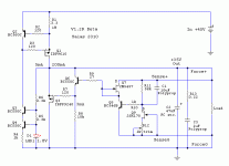
V1.2R beta
I evaluated some easy changes on V1.2 and I think they come across subjectively in a positive manner. At least on my 61dB Low MC phono. Pretty stable on the scope also. So I am calling the usual suspects with builds in hand to evaluate and confirm or not on their client applications. Lets call this the V1.2R(revisited) beta test. The changes are two. First the 33p-1k step circuit is deleted and the BJT error amp's base resistor is made to 1k. Second, the output network across the force lines becomes a combination of one electrolytic, a resistor and a film capacitor. Its not crucial to change the value of the Vref film capacitor or the value of the output film capacitor in existing builds for testing. Only to add the 47uF and change the Zobel's resistor to 0.22R. I attach an example. If you fancy beta testing, let me know your feedback.
I evaluated some easy changes on V1.2 and I think they come across subjectively in a positive manner. At least on my 61dB Low MC phono. Pretty stable on the scope also. So I am calling the usual suspects with builds in hand to evaluate and confirm or not on their client applications. Lets call this the V1.2R(revisited) beta test. The changes are two. First the 33p-1k step circuit is deleted and the BJT error amp's base resistor is made to 1k. Second, the output network across the force lines becomes a combination of one electrolytic, a resistor and a film capacitor. Its not crucial to change the value of the Vref film capacitor or the value of the output film capacitor in existing builds for testing. Only to add the 47uF and change the Zobel's resistor to 0.22R. I attach an example. If you fancy beta testing, let me know your feedback.
Attachments
I use 47V on the phono and 5k6 in its CCS cascoded tail. You just calculate whatever resistors in any Vout application that are able to feed circa 5mA to the LED. R9 or not, no real problem. R11 relative, no worries. Its just a 35V example to eyeball the changes. To test the V1.2R you just lift a leg from the 33p-1k feedback network, that will write it off circuit, you change the previous 27R or 33R BC546's base resistor to 1k and you strap a 47uF across your existent RC output. Not using only a 47uF, both. The lytic's added and the film cap RC Zobel remain. Its a system, and crucial to termination and stability. Even screwing the lytic in the force out connector will do for easy testing. If you like it, let me know. Then you can fix the changes. Else, you reverse them in a minute. If we all agree its positive, then V1.2R stays. Else, it does not graduate.
This seems a very logical upgrade to me.
The V1.2 with 47u EL output sounds warmer, with a fuller upper bass, lower mid presentation than the 10u film output that has much higher detail but can sound lean in some systems.
But why did you delete the 33p-1k step circuit ?
The V1.2 with 47u EL output sounds warmer, with a fuller upper bass, lower mid presentation than the 10u film output that has much higher detail but can sound lean in some systems.
But why did you delete the 33p-1k step circuit ?
Nice 'n' easy mod 
YouTube - Frank Sinatra - Nice "N" Easy
Even if 0.22 ohm resistors (not as big as the ones generelly used for pw devices) aren't that easy to find...
YouTube - Frank Sinatra - Nice "N" Easy
Even if 0.22 ohm resistors (not as big as the ones generelly used for pw devices) aren't that easy to find...
Last edited:
Even if 0.22 ohm resistors (not as big as the ones generelly used for pw devices) aren't that easy to find...
Parallel some sub 1R or other.
I have a 33r as R6 (BC546 base resistor).
I have no resistor between Q8 BC550C and Q6 2N5457.... must I place R9 27r there or can I experiment by just replacing R6 by a 1k ?
Refer to the V1.2R previous page's example designations, so its clear. Replace your 33R with 1k. 27R to 550C driver not crucial.
Its stable on the scope too. Slowly rising is the 546's Vbe changing with heat and both its tempco and K170's tempco. We could mini sink those and see if they are steadier for drift also I guess. In lower voltages the 27R was showing a slightly better damping theoretically but its not something I could find a practical difference for. Maybe in longer layout its good to damp the trace inductance to the 550's base though.
- Status
- This old topic is closed. If you want to reopen this topic, contact a moderator using the "Report Post" button.
- Home
- Amplifiers
- Power Supplies
- The simplistic Salas low voltage shunt regulator

