Hello George,
1/Is the top electrode sterling silver, or pure silver?
2/Is the Tungsten (bottom) electrode Pure Tungsten , Lanthanated Tungsten , Thoriated Tungsten , Rare Earth Tungsten , Ceriated Tungsten or Zirconiated Tungsten ?
3/Is the silver coil (solid or tube) silver ( pure or sterling) wire?
1/Is the top electrode sterling silver, or pure silver?
2/Is the Tungsten (bottom) electrode Pure Tungsten , Lanthanated Tungsten , Thoriated Tungsten , Rare Earth Tungsten , Ceriated Tungsten or Zirconiated Tungsten ?
3/Is the silver coil (solid or tube) silver ( pure or sterling) wire?
Repeating for those just joining the thread:
Please be sure to place your plasma tweeter *inside* a shielded, grounded enclosure.
All tubes capable of running a plasma tweeter create significant RF output.
A big tube like a 4-400 or an 813 is capable of substantial RF output.
ANY RF radiation beyond 100mw IS ABSOLUTELY ILLEGAL IN ALMOST EVERY COUNTRY IN THE WORLD. Plus you can interfere with all sorts of other communication and services at distances exceeding 1,000 miles away from you!!
The output of a plasma frequency is HIGH in RF Intermodulation products. Your output is NOT just on one single frequency!!
PLEASE PRACTICE GOOD RF PRACTICES - SHIELD AND GROUND YOUR PLASMA TWEETER. Place the RF tube inside a SHIELDED AND GROUNDED ENCLOSURE as well!
_-_-bear
Hello toshiba_nz,
both made of tungsten electrodes are 3.2 mm as it is used for welding.
You should only make sure that there are new standards are without radioactivity.
The coil I first made from pure silver, but it also works with copper coating insulation, 1.2 mm in diameter.
@ Bear,
you are quite right, such a device must be properly screened and because it set a high performance, but many services could interfere.
There are detailed rules for, a scanner should be in about 20 meter distance no more than a little noise or a low hum can see, my building does notmore than the Magnat MP-02 which my friend owns and which I also measured.
Until that is should be shielded his experiments in the short term.
My two devices are still working without an exchange of a part as at the beginning.
Greeting
George
toshiba_nz said:Bear, as long it as your equipment (that i'm interfering with) im fine with it.
")
Ya ya... have they put electricity into NZ yet?


I heard that they have?
Regardless, this isn't something to take lightly.
Interference is really not nice, and if you know you are or might be doing it, it is malicious. Since everyone reading this now knows, I hope no one wants to be malicious.
_-_-bear

Low frequency cut-off?
@George Green,
Hi George,
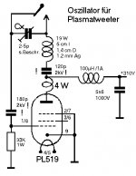
If you are still here ... I am considering an altered version of your plasma-tweeter design for e.g. a headphone but I'm wondering what the low cut-off frequency of the design is?
Also, I noticed the schematic shown below on the first page of your design description here at diyaudio. Would you happen to have simple formulas for calculating oscillation frequency etc. with other tubes like e.g. a lower power triode tube?
Best regards,
Jesper
@George Green,
Hi George,
If you are still here ... I am considering an altered version of your plasma-tweeter design for e.g. a headphone but I'm wondering what the low cut-off frequency of the design is?
Also, I noticed the schematic shown below on the first page of your design description here at diyaudio. Would you happen to have simple formulas for calculating oscillation frequency etc. with other tubes like e.g. a lower power triode tube?
Best regards,
Jesper
Attachments


@koldby
Hi,
Actually it's already been done.
Try: http://membres.lycos.fr/plasmapropulsion/Industrial_issues/Plasmasonic.htm
This solution operated at a maximum current of 100 uA and a voltage of 3 kV meaning a power release of 0.3 watts per channel (maximum).
Yes, there is an issue with proper shielding and high voltages - but imagine a membraneless superb headphone ....
Just out of curiosity: Can I ask you what your field of expertise is in electronic engineering?
Best,
Jesper
Hi Jesper
Very interesting articel. Looks as if it actually can be done.
I would still be concerned with the heat generated if the acustical output is high enough. I have made a couple of ecxperiments with plasma tweeters and they are very hot and not that loud. But still - maybe.....
Sure you can ask:
I am a trained electronic engeneer with development of high end audio electronic and loudspeakers as my main field. Have worked as consultant engeneer for Danish as well as forign companies. Nothing for the here and now though.
If you want to know more PM me.
Koldby
Hello Guys.......
I am going to set up some of this gear too. I have an old valve amp transformer (Yamaha organ) with 285-0-285 winding and that should do for H.T.
I will use TIG welding tips for the arcs and some ceramic tiles like George.
This should be cool. Has anyone else managed to get results like George has?
Cheers. (Sunny Queensland)
Re: Tuning plasma tweeter voltage/current
Hi CV, Yes if you 'charge couple' your load, Voltage and current will be (90deg?) out of phase.
Cheers.
CV said:Hi,
I think it was Mike who pointed out that for best results, the circuit should be tuned so that the ac voltage and current seen by the tube are out of phase. Any one know of any online references on this kind of thing? I may be able to borrow an ARRL handbook from somewhere if the material is in there too.
Cheers
cv
Hi CV, Yes if you 'charge couple' your load, Voltage and current will be (90deg?) out of phase.
Cheers.
Hi all!
At me it has turned out to make plasmatweeter, but there is one problem with category ignition how it is possible to make its automatic?
As my experience, rising the Ua to 500V or 600V will make the flame start automaticly.
Any micro-controller will not be needed.
..
Last edited:
In my ionofone operating anode voltage of 600V is included after the heating filament lamps, but the plasma still does not light itself, which generating the lamp you are using and what the voltage on the second grid, if you do not complicate the scheme to send vogor@yandex.ruAs my experience, rising the Ua to 500V or 600V will make the flame start automaticly.
Any micro-controller will not be needed.
..
- Status
- This old topic is closed. If you want to reopen this topic, contact a moderator using the "Report Post" button.
- Home
- Loudspeakers
- Planars & Exotics
- Plasmatweeter