Beta testing is still going on I added more stuff to the code here is what is new (sneek prewiev)
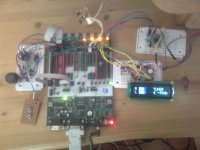
this is my test setup (dont have the real controller hardware yetIR Volume Control Ver.1.0 (c) Danzup (FarmTech Special) 0db to -63db lcd version
for Preamp Solid State version (tube version later) the warm up tube Timer is NOT Activ in this setup
This is a edit version of Danzup´s soft/hardware Post #4
http://www.diyaudio.com/forums/anal...controlers-source-selections.html#post1906703
Schematic Post#4 Zip
R/R2 with LCD !!! ONLY R/2R NOT SHUNT yet
Note !! to use this you have to build a half-wave rectifier see schematic
My change :
Added Backlight control auto or allways ON ( AUTO = off after ca 10 sec)
Added Learn new RC5 remote : You need a rc5 remote with min 10 buttons
Added Edit input select Text via lcd & Remote
Added New RC5 decoder ( Dont use Bascom GetRC5)
Added Vu Level meter on lcd see *schematic about hafe-wave for ADC6/ADC7 pins
Added Edit Vu level in menu 10-35 default is 20
Added total new lcd design for level meter/ input/volume in -db (0-63)
Added Save settings to eeprom on power off
Added Soft volume on power on/off & mute volume rissing/falling slowly
Menu :
Allways return to volume control via encoder on exit (auto exit menu after about 10 sec)
Volume : Turn encoder left/right to adjuse volume
Input : Turn encoder left/right to select what input you like to use (CD,TUNER,DVD or AUX)
Light : Turn encoder left/right to select Auto or On
New RC5 : Just turn encoder to enter the setup via LCD (11 step to add neww RC5 remote)
Edit Text : Just turn encoder to enter change Input select Text and use Remote via LCD to change it
Vu Level : Turn encoder left/right to adjuse level off input 10 - 35 default is 20
New RC5 remote :
Menu / select New rc5 and turn encoder
Now you will be ask to PUSH a button
If your remote is a RC5 it will continue the setup else PUSH MENU to exit (not a RC5 remote)
You need a remote with min 10 buttons to setup the controller
Power on/off , CH+ ,CH-, Vol+, Vol-, Mute, and 4 buttons for direct select input
When done it store the new remote in eeprom and use this rc5 setup
Edit input text :
Menu / Edit text and turn encoder (you need the remote to do the rest)
LCD will now show the Input text for input 1 on Line 1 line 2 show a Letter (A)
use Vol- to select the input text you like to edit (show on line 1)
To edit the text do this :
Use CH+ to scroll Letter UP / CH- is down
When you have the letter you like to use Press VOL+
now it show the new letter on line 2 you have letter & the next letter
use CH+ CH- to select next letter and Push VOL+ ect untill you have the text you like to use Max 7 chars
PRESS Mute to store the text for input in EEprom (if you have used all 7 chars it auto save the text use Vol- to select new text to edit or)
If you like to edit other input text use Vol- to select the input text and do the steps again (Ch+ CH- Vol+ ,mute)
If you are done edit text press POWER ON/OFF on remote ( Exit edit and return to normal)
Menu / Light Turn encoder Left/Right to select AUTO or ON
If AUTO it turn off baclkight after about 10 Sec
If ON backlight is allways ON
Menu / VU Level Turn encoder Left/Right to adjuse level on lcd 10 - 35 defalut is 20
This is a level change of the output to LCD meter you have 6 bars on lcd for VU meter
if your input is to high they dont show muts just on all time
try to decrese the level so MAX input light up the 6´th Bar with 5 ||||| bar signs
every bar is spit up in 5 bars signs |
IF YOU DONT KNOW HOW TO DO THIS DONT DO IT !!!!!!!!!!
How to connect the half-wave rectifier to Atmega16 :
On the controller board you have PIN30/31 for LED display
M16 ADC6 ADC7 pins
(if you build your own then you know where ADC6/7 is)
You need to connect this to pins to half-wave rectifier ADC6 and ADC7 and connect Gnd to Gnd on board
it can use the +5volt & GND from board
The L/R & GND input on half-wave rectifier cant be connectet to Direct output
Hope you report any errors or change you like to have , and I´ll try to make them
Attachments
Last edited:
Hi Kim
...Added New RC5 decoder ( Dont use Bascom GetRC5)...
Very interesting feature...
Could you post a code for this procedure?
Easy just look at post http://www.diyaudio.com/forums/anal...trolers-source-selections-31.html#post2318106
dont use INT1 just timer0
but here is the code clean from other stuff
Code:
$regfile = "m16def.dat"
$crystal = 8000000 ' **** MUST BE 8Mhz for rc5 to work via timer0 setup  (or edit values)
$hwstack = 32
$swstack = 30
$framesize = 34

Config Lcdpin = Pin , Db4 = Porta.2 , Db5 = Porta.3 , Db6 = Porta.4 , Db7 = Porta.5 , E = Porta.1 , Rs = Porta.0
Cursor Off
Config Lcd = 16 * 2
Cls

  Config Portd.3 = Input
  Input_pin Alias Pind.3                                    ' TSOP1736
  Config Timer0 = Timer , Prescale = 8
  On Timer0 Timer_irq
  Const Timeconst = 78
  Enable Timer0
  Enable Interrupts


  Const Samples_early = 8
  Const Samples_late = 12
  Const Samples_min = 3


  Dim Sample As Byte
  Dim Ir_lastsample As Byte
  Dim Ir_bittimer As Byte
  Dim Ir_data_tmp As Word
  Dim Ir_bitcount As Byte
  Dim Address_rc5 As Byte , Command_rc5 As Byte , Rc5_flag As Bit


Do

If Rc5_flag = 1 Then

   Reset Rc5_flag
   Command_rc5 = Command_rc5 And &B01111111
   'Cls
   'Lcd Address_rc5 ; " " ; Command_rc5
'your code here
End If

Loop


Timer_irq:
  Timer0 = Timeconst
  Sample = Not Input_pin


  If Ir_bittimer < 255 Then Incr Ir_bittimer
  If Ir_lastsample <> Sample Then
  If Ir_bittimer <= Samples_min Then
     Ir_bitcount = 0
  Else
     If Ir_bittimer >= Samples_early Then
         If Ir_bittimer <= Samples_late Then
            Shift Ir_data_tmp , Left , 1
            Ir_data_tmp = Ir_data_tmp + Sample
            Incr Ir_bitcount
          Else
            Ir_bitcount = 1
            Ir_data_tmp = Sample
          End If
          Ir_bittimer = 0
       End If
     End If


     If Ir_bitcount = 1 Then Ir_bitcount = Ir_data_tmp.0
     If Ir_bitcount >= 14 Then
       Timer1 = 0
       Command_rc5 = Ir_data_tmp
       Shift Ir_data_tmp , Right , 6
       Address_rc5 = Ir_data_tmp And &B00011111
       Command_rc5.6 = Not Ir_data_tmp.6
       Command_rc5.7 = Ir_data_tmp.5
       Set Rc5_flag
       Ir_bitcount = 0
       Timer1 = 15000
       Start Timer1
     End If

  End If

  Ir_lastsample = Sample

Return
Last edited:
I've tested FarmTech's firmware and I can say only  .
.
Exellent work. Fast, good and simple to use. Real .
.
Danzup gave us a lot of possibilities to choose what we want. LED or LCD display, four to eight inputs, different AT microcontrollers, pushbuttons or rotary encoder, different devices for signal attenuation, tubes or solid state. I'm sure I missed something.
Now we have one more choice: FarmTech's firmware. Who could ask for more?
.Exellent work. Fast, good and simple to use. Real
.Danzup gave us a lot of possibilities to choose what we want. LED or LCD display, four to eight inputs, different AT microcontrollers, pushbuttons or rotary encoder, different devices for signal attenuation, tubes or solid state. I'm sure I missed something.
Now we have one more choice: FarmTech's firmware. Who could ask for more?
I've tested FarmTech's firmware and I can say only
Exellent work. Fast, good and simple to use. Real
Danzup gave us a lot of possibilities to choose what we want. LED or LCD display, four to eight inputs, different AT microcontrollers, pushbuttons or rotary encoder, different devices for signal attenuation, tubes or solid state. I'm sure I missed something.
Now we have one more choice: FarmTech's firmware. Who could ask for more?
Hi,
congrats & thank you to all experts!
Nonexperts would be very grateful for transparent overview of final solution (incl. all alternatives, possibilities).

Where I can get this firmware?
HI,
Its not public yet just a few more test then I´ll post the HEX/BIN file for this
Version Only for R/2R-shunt with LCD Danzup M16 controller as in post#4
there will be 2 versions
1 for tube with "warming up tubes time" and a version for solid state amp
Then I see if someone like other versions for PG2310 or motorpot but still ONLY for M16 with LCD
think all will be ready before the weekend (I hope)
Hi Kim
...Added New RC5 decoder ( Dont use Bascom GetRC5)...
Very interesting feature...
Could you post a code for this procedure?
Its a nice setup of RC5 , less rom space than Bascom GetRc5 command
and we dont need the INT1 config
Kim
That IC is a great discovery !!!!
Keep on the good job !
I like`it !
Yep it a nice chip to use
Allmost done with firmware now , hope you like it
All in 1 version for LCD Version only (be cuz the Vu Meter) R/2R - Shunt - tube or solid state peramp (Tube = warming up tubes 60 sec)
all can be setup i menu
Have a nice weekend
Kim
Last edited:
")
Here is my latest version of fimware for my preamp and it also works with any Elector pga 2311 preamp as published in 4/2004 issue of this magazine.So far it works fine and does not hang anymore, but I was not able to receive any sony rc code. I,m sure, this time I made anything right, so maybe this decoder is wrong or something else.Anyway I can't do anything more.
Attachments
As you already know, I had great luck to be beta-tester of FarmTech's firmware. I'm not expert, I'm just common user, so I tried to do my part of deal the best I could.
I must say it was easy. FarmTech made brilliant firmware. Everything he sent to me worked without problems. I tried to outwit his firmware, but it was impossible.
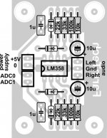
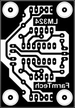
Also, I work like . I don't have much free time for my hobby, so I had to steal time from my job. FarmTech wrote program for VU meter on LCD. It looks wonderfull, but you must have extra hardware for this feature. He gave schematic for half-wave rectifier in post #302. I made PCB.
I must say it was easy. FarmTech made brilliant firmware. Everything he sent to me worked without problems. I tried to outwit his firmware, but it was impossible.
Also, I work like
. I don't have much free time for my hobby, so I had to steal time from my job. FarmTech wrote program for VU meter on LCD. It looks wonderfull, but you must have extra hardware for this feature. He gave schematic for half-wave rectifier in post #302. I made PCB.Attachments
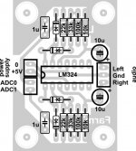
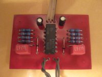
My problem is living in small city without electronic store. I must go to Belgrade even for a single resistor. I hadn't LM358, but I had LM324, so I made PCB. I also didn't have BAT42, so I soldered 1N4148.
Attachments
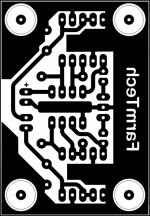
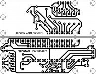
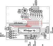
I still use my first PCBs from page 9 of this thread, but for the future I need slim and compact PCB for controller. I'm too old to use SMD, so I made new PCB. It also uses through hole components. I must warn you that this is amateur project, it's not optimised, there are no gerber files, it's just for DIY use. Simple, single sided.
Attachments
- Home
- Source & Line
- Analog Line Level
- Yet another Volume controlers and source selections