which parameters do you think might benefit from matching?
It's helpful to select the Idss of the Jfets for 7-8 mA.

Is there any advantage in matching 9240s & 240s in the F5?
I just buy my 240/9240 from the same batch and havent had any problems.
I do find in multiple pair outputs that one pair of transistors turn on first.
But we are talking millivolts difference and the source resistors balance out any differences.
I just buy my 240/9240 from the same batch and havent had any problems.
I do find in multiple pair outputs that one pair of transistors turn on first.
But we are talking millivolts difference and the source resistors balance out any differences.
Multiple pairs of outputs is different than the stock circuit. Then they should be matched.
Is there any advantage in matching 9240s & 240s in the F5?
Those two are impossible to match - manufacturer never meant them to be a complementary pair. They are very different... The beauty of F5 design is that they don't need to be matched at all - that's why we have those two 5k trimm-pots.
without load
with load of "usual" A class channel it's more in range of 1,2-1.25
Duncan's Amp Pages , download PSU Designer , and you'll know , after some play with proggie
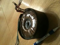
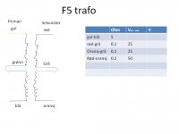
Here`s what I worked on: By ohm-ing the primary and secondaries of the tranny I used the button in PSUD2 where you can enter ohm-values for trannies. Then I made a filter in PSUD2 simulating including a couple of filter-chokes that I have. The chokes are 22mH/200mOhm/7Amax. Now, in PSUD2 you cannot make a +/- supply so I did it like in the picture. At 2,6A load the current thru the choke is 4A. I have tested my chokes and they do not buzz until 7A in a powersupply like this.
Well, I get +\- 20V output if I do it like this. Do you think it is suitable for an F5 project?
Attachments
Those two are impossible to match - manufacturer never meant them to be a complementary pair. They are very different... The beauty of F5 design is that they don't need to be matched at all - that's why we have those two 5k trimm-pots.
Sorry, to be clear, I didn't mean matching the Ps to the Ns, but more I meant channel matching, ie the left P to the right P and the left N to the right N.
On the rails of my F5 I have 24VDC, my transformer is a 500VA 2x18v Toroidy, very satisfied with it, good build quality and completely silent.
The power supply in my F5 is a CLC (10mH 0.07ohm) and my mains voltage is 234VAC
Hi danny,
Interested to know the current rating of the L in your CLC .
Any link to the purchasing source ?
thanks
kp93300
Last edited:
Hi,The chokes are 22mH/200mOhm/7Amax. Now, in PSUD2 you cannot make a +/- supply so I did it like in the picture. At 2,6A load the current thru the choke is 4A.
the output voltage of a choke input filter is very dependant on the current drawn through it.
Change the 2.6A to 5.2A for maximum draw on one polarity of the PSU (5.2A into 4ohm).
Then change the 2.6A down in steps of ~0.5A, down to 0.1A.
How does the output voltage vary over that range of output currents from 100mA to 5200mA?
Question on Thermistor in the F5 Powersupply
Hi,
I am all set to make the F5. I have assembled the boards, got the heatsinks, toroid etc.
I am going through the detailing, before I start connecting up. I have noticed that in the suggested "First Watt PS 0 R1 Power Supply" for F5, there is a CL60 Thermistor between the power supply ground and chassis ground.
I have two questions. What is the purpose of this Thermistor and should it be mounted on the Mosfet heatsinks or left free standing?
Thanks in advance.
Cheers.
Anil
1) Stop earth loops.
the Power Thermistor connecting Safety Earth to Audio Ground is to meet the requirement of:1) Helps to prevent inrush current on startup from popping fuse.
all exposed conductive parts must be connected to Safety Earth.
the Power Thermistor connecting Safety Earth to Audio Ground is to meet the requirement of:
all exposed conductive parts must be connected to Safety Earth.
Yes, but that can be done without thermistor.
So yes you are right, but the reason a thermistor is used and not just a direct wire connection is to stop audible earth loops with interconnected equipment.
So the complete answer is: A thermistor is used to meet the requirement of "all exposed conductive parts must be connected to Safety Earth". The added benefit of using a thermistor (and not directly connected) is to minimise audible earth loops.
The thermistors on the primary (mains) side of the transformer are to reduce inrush current as Renron stated.
Hopefully this clears everything up.
Last edited:
Hi,
the output voltage of a choke input filter is very dependant on the current drawn through it.
Change the 2.6A to 5.2A for maximum draw on one polarity of the PSU (5.2A into 4ohm).
Then change the 2.6A down in steps of ~0.5A, down to 0.1A.
How does the output voltage vary over that range of output currents from 100mA to 5200mA?
I did the excercise in PSUD2 and plotted the Vout values in a graf.
I also did a current step sim in PSUD2 jumping from 2,6A to 5,2A current draw. I`m not sure how to interpret the data though.
If the F5 amp is biased to 2,6A (both channels), will the amp still vary the current draw from the supply from 0,1A to 5,2A. I thought that was more like class AB behavior.
Attachments
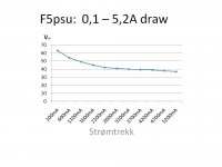
That looks typical of a choke input filter.
the voltage holds well over the current range from 2A to 5A.
But as the current demand falls below 2A the voltage presented to the amplifier rises to eventually reach 1.4 * Vac (offload), whereas the on load voltage is ~0.9 * Vac(on load).
the range of current that a choke input filter can supply and hold close regulation on the voltage is quite narrow.
As the current demand falls the required Inductance rises.
Double your choke Henries and plot out that 100mA to 5200mA graph.
ClassA amplifiers modulate the supply rail current just like all other ClassAB and ClassB, except ClassA does it gently with few harmonics. ClassAB and ClassB do it quite abruptly and generate lots of HF harmonics.
There are exceptions to this modulation of rail currents.
A fully balanced design draws nearly constant current from the supply rail/s
A SE design that returns the speaker to the supply rail rather than to the ground makes a very good attempt at constant current draw.
- Home
- Amplifiers
- Pass Labs
- F5 power amplifier