Yes for the placement of the resistor, but wait until you have the power transformer sorted, you might not have to do anything more than that.
I am always worried about bolt isolation for toroids, unless the isolator is a T barrel, nylon isolator in the proper sized hole. The bolt is a core short if it happens and current draw and subsequent fire are only seconds away.
I am always worried about bolt isolation for toroids, unless the isolator is a T barrel, nylon isolator in the proper sized hole. The bolt is a core short if it happens and current draw and subsequent fire are only seconds away.
Before i try the 100 ohm resistor i just wanted to confirm that having the signal grounds of both channels connected together at one star is the correct way to ground a dual mono amp (that is how my amp is presently wired). Would i benefit from keeping the grounds of the two channels seperate?
cheers,
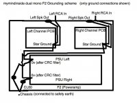
mymindinside
cheers,
mymindinside
Here are some pics of my Dual Mono F2
The SG (Signal Grd) has the phono grd and speaker ret attached to it. The GO (Grd Out) goes to GRD on the power supply board. I have zero hum and it is as quiet as a mouse.
Rob.
The SG (Signal Grd) has the phono grd and speaker ret attached to it. The GO (Grd Out) goes to GRD on the power supply board. I have zero hum and it is as quiet as a mouse.
An externally hosted image should be here but it was not working when we last tested it.
An externally hosted image should be here but it was not working when we last tested it.
An externally hosted image should be here but it was not working when we last tested it.
Rob.
Last edited:
Hi,
the third wire (PE) in the mains cable must be permanently connected to the chassis.
All exposed conductive parts must be connected to chassis.
That includes the RCA returns (grounds) and the speaker returns (grounds).
Another reason for not using RCA/Phono plugs/sockets.
the third wire (PE) in the mains cable must be permanently connected to the chassis.
All exposed conductive parts must be connected to chassis.
That includes the RCA returns (grounds) and the speaker returns (grounds).
Another reason for not using RCA/Phono plugs/sockets.
Puffin, where is GO on the board? i am connecting my power supply ground to the hole marked GND right next to the one marked SG. SG has my rca gnd and the speaker return connected to it. ditto on the other channel. i have just finished rewiring to this setup and now have a loud hum when both channels are connected. would you mind explaining how the grounds of your two channels were connected.
Andrew, i understand the need to connect all exposed conductive parts to earth. If i am not mistaken, In the Firstwatt F2 this is done by connecting the 0v rail to the chassis through a thermistor, and connecting the chassis to earth. the 0v rail is connected to the RCA ground and the Speaker return.
In the photos of the Firstwatt F2 it looks like each channel has its own signal star and a trace leading from this star to the 0v rail. this exactly what i have done now but i have a loud hum, much louder than my previous wiring setup where i had connected the signal grounds of both channels together at one star.
Please tell me what i'm doing wrong....
cheers,
mymindinside
I just noticed that the PSU of the right channel is 1volt lower than the left one. the voltage is identical (to .10 volt) after the rectifiers, and till the R part of the CRC PSU. it is the identical when measured after the resistor but drops by a volt or so when measured at the next capacitor in the PSU. This drop is not there on the other (left channel). could this difference in voltage be contributing to the hum? what could be the cause?bad filter cap?
In the photos the PSU channel with the voltage drop is the one closer to the center of the case.
cheers,
mymindinside
In the photos the PSU channel with the voltage drop is the one closer to the center of the case.
cheers,
mymindinside
Puffin, where is GO on the board?
i am connecting my power supply ground to the hole marked GND right next to the one marked SG. SG has my rca gnd and the speaker return connected to it. ditto on the other channel. i have just finished rewiring to this setup and now have a loud hum when both channels are connected. would you mind explaining how the grounds of your two channels were connected.
Andrew, i understand the need to connect all exposed conductive parts to earth. If i am not mistaken,
In the Firstwatt F2 this is done by connecting the 0v rail to the chassis through a thermistor, and connecting the chassis to earth. the 0v rail is connected to the RCA ground and the Speaker return.
In the photos of the Firstwatt F2 it looks like each channel has its own signal star and a trace leading from this star to the 0v rail. this exactly what i have done now but i have a loud hum, much louder than my previous wiring setup where i had connected the signal grounds of both channels together at one star.
Please tell me what i'm doing wrong....
cheers,
mymindinside
Sorry, the board is marked GRD, not GRO, but the connection is the same.
In the Firstwatt F2 this is done by connecting the 0v rail to the chassis through a thermistor, and connecting the chassis to earth. the 0v rail is connected to the RCA ground and the Speaker return.
I cannot see a thermistor in this pic? or maybe it is my eyesight.
An externally hosted image should be here but it was not working when we last tested it.
In the photos of the Firstwatt F2 it looks like each channel has its own signal star and a trace leading from this star to the 0v rail. this exactly what i have done now but i have a loud hum, much louder than my previous wiring setup where i had connected the signal grounds of both channels together at one star.
I cannot see that either?
Last edited:
You can see how it's done on page 9 of the F1's service manual: http://www.firstwatt.com/pdf/prod_f1_srv.pdf. In the picture the thermistors are the fat green discs. On page 11 you can see the top layer of the PSU pcb, ans afaik they're all the same in the Fw amps. If you rotate the pdf 90° clockwise (clockwise, the caption is on the left then), the pcb is orientated just like in the picture in question. On the bottom you see two ports labeled AC, that's where the mains get connected (after fuse+switch). Next to these two ports you see TH1 and TH2, these are the thermistors connecting the circuit ground to earth ground. In the picture you can spot one of these thermistors on the left, on the right it's concealed by the mains wires.
The other two thermistors at the top of the pcb are used for softstart and to select the voltage (120V/240V primaries parallel/series connection), just like in the schematic.
The other two thermistors at the top of the pcb are used for softstart and to select the voltage (120V/240V primaries parallel/series connection), just like in the schematic.
Hi Puffin,
i saw the Firstwatt grounding scheme (signal ground star and a trace leading to the 0v rail) in the F2 service manual in the pcb layout.
does my wiring setup match yours? can you think of anything i have done done wrong which is giving me a loud hum (disappears with any one input rca disconnected)
the help is much appreciated
cheers
mymindinside
Ok, let me ask a specific question.
what resistance reading should i get when i measure between the 0v rails of the two channels. if i measure without any inputs connected i get 18 ohms. this is the series resistance of two cold CL60's which connect the two 0v rails together, with the chassis connected in between the thermistors. if i measure with rca inputs connected then i read less than 1 ohm. i suppose this is because the 0v rail is connected to the pcb ground which is connected to the rca input ground and the left and right rca input grounds are connected at the preamp.
is this low reading with inputs connected normal or am i missing something?
cheers,
mymindinside
My amps measure infinity between grounds without inputs connected, and 0 ohms with the plugs inserted. Such is dual mono ") and no chassis. Which basically means there is no other shared connection to ground apart from the input RCAs.
and no chassis. Which basically means there is no other shared connection to ground apart from the input RCAs.
Can you try drawing a diagram of how your grounds tie together? Just putting it on paper will give you a few ideas.
and no chassis. Which basically means there is no other shared connection to ground apart from the input RCAs.Can you try drawing a diagram of how your grounds tie together? Just putting it on paper will give you a few ideas.
hummmmmm
Puffin,I don't like the F2 that you postered in a picture. It is not an example of secure earthing because the connection to the chassis should be mechanically strong, not soldered. Another issue is that the grounding bolt must be used ONLY to support the grounding wire against the chassis wall/chassis/whatever and not for bolting the AC socket
Puffin,I don't like the F2 that you postered in a picture. It is not an example of secure earthing because the connection to the chassis should be mechanically strong, not soldered. Another issue is that the grounding bolt must be used ONLY to support the grounding wire against the chassis wall/chassis/whatever and not for bolting the AC socket
......Another issue is that the grounding bolt must be used ONLY to support the grounding wire against the chassis wall/chassis/whatever and not for bolting the AC socket
looks good enough for me
imagine that contact at AC socket is good enough to melt green wire coming to it .
I'll say it...LOL. I believe the picture is taken from 6moons audio reviews: FirstWatt F2 and it's one of the original units...
Edit: Which is not to say that what you said is wrong.
Edit: Which is not to say that what you said is wrong.
In the F1 manual Nelson says that the Chassis is tied to Earth at the IEC Receptacle as well as by the 4 standoffs on the PSU PCB. Strictly though, regiregi22 is right, and the connection should be made with a dedicated bolt.
i will post a diagram of my wiring scheme as soon as i make it.
cheers,
mymindinside
i will post a diagram of my wiring scheme as soon as i make it.
cheers,
mymindinside
- Status
- This old topic is closed. If you want to reopen this topic, contact a moderator using the "Report Post" button.
- Home
- Amplifiers
- Pass Labs
- Transformer Screen & Signal Grounding Issues