My apologies if this has been covered but my search has not helped.
After originally getting a good bias setting on my left channel, I made a dumb error and cooked some components. In particular, R111/R112 on cviller v2.0 board got red hot and other components seem to have died.
I am now am trying to isolate the bad components and would love to do this without unsoldering everything on the board. However, I'm getting different resistance readings between the good board and bad one in a number of places so I'm not making much progress.
Has anyone posted any guidance on this? E.g., the expected resistance values at different points or how to check the active components.
Sorry if this is a dumb question, I'm new at this.
Any help is appreciated.
check resistance of the center pin of the transistors to ground to make sure it is not 0.
The first time in operation: my full F5 to drive the FW250 midwoofers
Boahhhh!!!!!
Just on the right time: after one year beeing unemployed (I had to solve my shock loosing the job by Studer), I will begin a new job next week.
As you can see: I needed this year also to consolidate my HiFi.
In the rare free time in the future, I gonna finish some enclosures and cleanup the whole setup....
Franz
An externally hosted image should be here but it was not working when we last tested it.
Boahhhh!!!!!
Just on the right time: after one year beeing unemployed (I had to solve my shock loosing the job by Studer), I will begin a new job next week.
As you can see: I needed this year also to consolidate my HiFi.
In the rare free time in the future, I gonna finish some enclosures and cleanup the whole setup....
Franz
You should bridge like I posted -- at lower rail voltage (+/-16V) and higher bias (2A per FET).
That means each half of the bridge is now optmised for 3 ohms.
(I always deduct 4V from the rail voltage as my "clipping" voltage.)
Patrick
I saw your schematic with the Toshiba outputs.
If I use the IRFs, can I "X" the spot between two sets of boards at R1-R2 and get a balanced board (and use 16V), or do I need bigger changes than that in terms of resistor values?
The first time in operation: my full F5 to drive the FW250 midwoofers
......
Franz
Looking good and congrats on your new job.
Cheers,
Dennis
Troubleshooting
Thanks Westend. I probably should have been more specific. The only troubleshooting I've done before is with tube amps where I could pull and test the tubes separately.
I did replace the burned resistors and was measuring the differences between the boards. For example, the differences I'm seeing across some resistors are:
R22 130 165
R5-8 11.8 28.4
R113 1.8 47.4
Also, there are big differences across the legs of Q103 and Q104.
I guess the question is whether there is an easy way to check whether the active components are good either in or out of the circuit. I'll go ahead and start checking the resistors individually.
Regards,
Stuart
Thanks Westend. I probably should have been more specific. The only troubleshooting I've done before is with tube amps where I could pull and test the tubes separately.
I did replace the burned resistors and was measuring the differences between the boards. For example, the differences I'm seeing across some resistors are:
Bad Good
R114 1.6 47.4R22 130 165
R5-8 11.8 28.4
R113 1.8 47.4
Also, there are big differences across the legs of Q103 and Q104.
I guess the question is whether there is an easy way to check whether the active components are good either in or out of the circuit. I'll go ahead and start checking the resistors individually.
Regards,
Stuart
I took out R6 and R7. Mr. Pass has a post on this and says you loose very little. It's not really clear to me what I lost vs. what I gained.
If this simple change in the feedback resistors is so helpful and has so little downside, why not make it the original design? There must be an issue or a lot more people would do it.
If someone understands the real changes in removing R6 and R7, I'd appreciate understanding it better.
Hi,
The reason for paralleling R5/R7 and R6/R8 was to enable the use of lower wattage resistors. You could replace each 100ohm 3W pair with a 50ohm 5watt+ resistor. Removing a 100R without changing the remaining 100R effectively reduces feedback (increasing gain/distortion). You should also change R1 & R2 from 10R to 20R in order to keep the ratio of feedback:source at 5:1. (50R:10R, 100R:20R, etc.)
You should also change R1 & R2 from 10R to 20R in order to keep the ratio of feedback:source at 5:1.
You may have overseen, that R1 and R2 are the source resistors for the input fets and are responsible for the gain of the first stage (just read Papa's pdf). Dont change their value only looking at the feedback voltage divider!!!
Removing one of the 100R resistors simply reduces feedback and gives you 6dB more gain (dont forget to justify the idle current after the mod).
You can be sure: the distortion is still very very low (your speakers will have higher distortion). Should you like it this way: everything is green!
Franz
Last edited:
Today, when I started the construction works for the full F5 with the heathsinks from an old Telewatt SA600 amp, I installed 3 pairs of 2SK2013 / 2SJ313, as the heathsinks had all this nice M3 holes:
But stop!
I have prepared a 2 x 18VAC / 500VA tranny, wich will result in about 24VDC.
Isn't 20V the absolute max for vds for this fet's?
Sh....
So, I was building the IRFP based F5 and I miss (for the moment) the chance to directly compare this solution with the stock F5 I built for a friend some weeks ago.
Franz
An externally hosted image should be here but it was not working when we last tested it.
But stop!
I have prepared a 2 x 18VAC / 500VA tranny, wich will result in about 24VDC.
Isn't 20V the absolute max for vds for this fet's?
Sh....
So, I was building the IRFP based F5 and I miss (for the moment) the chance to directly compare this solution with the stock F5 I built for a friend some weeks ago.
Franz
Last edited:
Is it as simple as this ? One end shown for example...
It looks correct, yes.
Franz
You may have overseen, that R1 and R2 are the source resistors for the input fets and are responsible for the gain of the first stage (just read Papa's pdf). Dont change their value only looking at the feedback voltage divider!!!
Removing one of the 100R resistors simply reduces feedback and gives you 6dB more gain (dont forget to justify the idle current after the mod).
You can be sure: the distortion is still very very low (your speakers will have higher distortion). Should you like it this way: everything is green!
Franz
I have reduced feedback via the removing one of the 100R a while back, but didn't touch anything else, except the bias. What do you mean by "justify the idle current?"
Question on added MOSFET pair for F5 - Peter Daniel's boards.
I have a spare set of IRF MOSFETS and figured I would play around and see how I like the sound/power with another pair per channel.
Is it as simple as this ? One end shown for example...
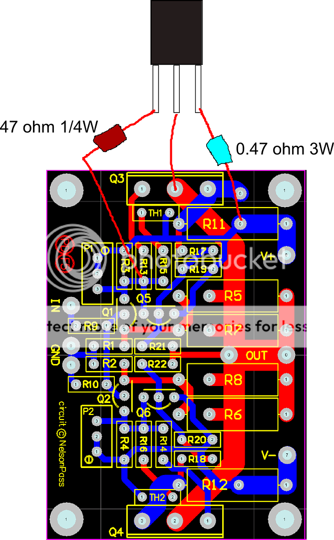
That looks good to me
You may have overseen, that R1 and R2 are the source resistors for the input fets and are responsible for the gain of the first stage (just read Papa's pdf). Dont change their value only looking at the feedback voltage divider!!!
Removing one of the 100R resistors simply reduces feedback and gives you 6dB more gain (dont forget to justify the idle current after the mod).
Franz
Hi Franz,
My understanding about the 5:1 feedback:source ratio came from my betters, most recently EUVL's comments on his FET balancing. See Nelson Pass's post#3731
Alternatively, you can increase the value of the Source resistors to 1 ohms,
and increase the value of the feedback resistors from 2 X 100 ohms and 10
ohms to 1 X 100 ohms and 22 ohms.
The lower amount of feedback will warm the sound up, and you can keep
increasing proportional values in the feedback loop if you wish.

My understanding about the 5:1 feedback:source ratio came from my betters, most recently EUVL's comments on his FET balancing. See Nelson Pass's post#3731
I missed this post. One day, I started to read the whole thread, but I stopped after some hours
In the meantime, I run my "big" F5 and also the Mini F5 with reduced feedback (100R).
It is interesting: to drive my speakers at the same level, the gain of the amp is more important than the power (also I can adjust the crossover by some dB's).
All amps have to have about the same gain to find a linear combination, but the woofers are needing more power than the horns.
The 2SK2013 and 2SJ313 mini version are driving the horns without any problem!
Franz
/Edit: it is simply fantastic, how everything is fitting together now (soundwise)
Last edited:
You may have overseen, that R1 and R2 are the source resistors for the input fets and are responsible for the gain of the first stage (just read Papa's pdf). Dont change their value only looking at the feedback voltage divider!!!
Removing one of the 100R resistors simply reduces feedback and gives you 6dB more gain (dont forget to justify the idle current after the mod).
You can be sure: the distortion is still very very low (your speakers will have higher distortion). Should you like it this way: everything is green!
Franz
Thanks for your post.
Do you have a feel for whether a "simple" X version can be done by "X"ing the R1 and R2 between two stock F5 boards? I've seen Patrick's build, but that uses the Toshiba outputs. I'm trying to see if anyone has "X"ed the IRF outputs.
Sorry, I never Xed some pass circuit up to now!
But today I paralleled the output devices 2SK2013/2SJ313 of my Mini F5:
Yes, it is better.
The additional current seems to be needed to drive the speakers in a very controlled matter and is resulting in a better soundstage.
Now it is the circuit Juma recommended me some days (weeks?) before: +-15VDC rails, 400mA per output device.
Franz
But today I paralleled the output devices 2SK2013/2SJ313 of my Mini F5:
An externally hosted image should be here but it was not working when we last tested it.
Yes, it is better.
The additional current seems to be needed to drive the speakers in a very controlled matter and is resulting in a better soundstage.
Now it is the circuit Juma recommended me some days (weeks?) before: +-15VDC rails, 400mA per output device.
Franz
Last edited:
Guys,
I was wondering what rectifier configuration is recommend for Class A amps like F5. The F5 manual shows a bridge for each secondary joined together (dual full wave bridge) and the Burning Amplifier manual shows one bridge common to both secondaries, with the secondaries tied together to form the ground (dual full wave and a centre tapped transformer). I guess the single bridge means less voltage lost at the diodes and hence lower heat (esp for class A), but what is the advantage of dual bridge?
PS I tried searching for this but couldn't find it.
Hi everyone, Recently i tried to plug my headphone into F5, and notice there is zyyyyyyyyyyyyy~ sound from one of the channel while another channel no such problem. What is the problem that might causing this. perhaps not ground issue because i am using star ground symmetrically on both channel.
I tend to move around the signal cables around and notice that the noise will going louder when i move it near to the heat-sink. But take in consideration of the other channel's signal wires is lay on heatsink, which has no problem at all.
I tried to measure the DC offset, it's just around 4~5mv something.
Any other way to troubleshoot?
- Home
- Amplifiers
- Pass Labs
- F5 power amplifier