Hi , I just had a debate with my friend about bracing a speaker box.
He says that the minimum amount of bracing ( like 1 cross brace at the middle ) is enough , and that adding extra bracing would color the sound because the air is moving in many random directions and reflect off the braces .
While I said that the more bracing the better ( like B&W matrix method ... magico mini bracing method ... ) to achive zero panel resonance .
So what do you think ?
How about something like this for bracing overkill :
An externally hosted image should be here but it was not working when we last tested it.
Last edited:
My current project has small boxes (only 5.5L per driver) so does not need extensive bracing, however what I did find was when I did put a brace in (in the only practical place which was right smack in the middle), that I did pick up a fairly significant reflection off the brace back through the driver cone.
Note that this brace (a piece of 1" square oak) was right behind and in the middle of the driver (probably only 7cm from the back of the driver.
So yes if you have braces directly behind your drivers they may cause reflections that come back at you through the speaker, though the layout you have shown I don't think this will be much of a problem. Before gluing them in place though (if possible) I'd do some near filed measurements with and without the braces, and moving their position around). I'd suggest rather than using square braces that you instead use some dowel (broom handle would probably be ok). This should still provide the torsional stiffness you require and should minimise the effects of reflections off the braces
Did you explain to your friend that it was box resonation causing colouration that the braces were intended to stop. I suspect that whilst improper bracing could make things worse, doing the job properly whilst it will change the sound, will be removing colouration, not adding it
Tony.
Last edited:
the braces appear square only in the sketch , they won't be.
I'm aware of the fact that bracing behind the woofer might cause reflections , I gave the woofer some breathing space behind . ( but in the magico mini the braces are behind the woofer ... like an inch behind ... )
So instead of the early reflections if the braces are dead behind the woofer , there are no drawbacks right ?
I mean look at the magico mini box ... or the B&W matrix that looks like a bee hive right ?
I'm aware of the fact that bracing behind the woofer might cause reflections , I gave the woofer some breathing space behind . ( but in the magico mini the braces are behind the woofer ... like an inch behind ... )
So instead of the early reflections if the braces are dead behind the woofer , there are no drawbacks right ?
I mean look at the magico mini box ... or the B&W matrix that looks like a bee hive
My current project has small boxes (only 5.5L per driver) so does not need extensive bracing, however what I did find was when I did put a brace in (in the only practical place which was right smack in the middle), that I did pick up a fairly significant reflection off the brace back through the driver cone.
Tony.
Hello
How does this reflection appear?

Internal reflections off of braces is unlikely to be an issue, I don't think, at least not compared to vibrating panels.
Also, a little experimenting with braces and an accelerometer (and a meauring system) demonstrates that the cross braces as you show don't actually do nearly as much as would rectangular (yes!) braces attached directly to the walls, to stiffen the wall surfaces as much as possible (not just at a point on the end of the dowels). Try to glue the braces lengthwise to the panels, with ends also attached to walls, so as to leave the smallest expanse of panel unbraced as possible. If the walls were drum heads, you'd want them to be the smallest area drumheads as possible.
Also, a little experimenting with braces and an accelerometer (and a meauring system) demonstrates that the cross braces as you show don't actually do nearly as much as would rectangular (yes!) braces attached directly to the walls, to stiffen the wall surfaces as much as possible (not just at a point on the end of the dowels). Try to glue the braces lengthwise to the panels, with ends also attached to walls, so as to leave the smallest expanse of panel unbraced as possible. If the walls were drum heads, you'd want them to be the smallest area drumheads as possible.
Vibrating panels is a far more serious issue than some very minor internal reflections.
Generally the more bracing the better. Reflections will be minimal - compare the wavelengths invloved with the size of the braces.
I would round any edges off and make sure there's plenty of air flow. You bracing diagram looks very good.
Generally the more bracing the better. Reflections will be minimal - compare the wavelengths invloved with the size of the braces.
I would round any edges off and make sure there's plenty of air flow. You bracing diagram looks very good.
Also, a little experimenting with braces and an accelerometer (and a meauring system) demonstrates that the cross braces as you show don't actually do nearly as much as would rectangular (yes!) braces attached directly to the walls, to stiffen the wall surfaces as much as possible (not just at a point on the end of the dowels). Try to glue the braces lengthwise to the panels, with ends also attached to walls, so as to leave the smallest expanse of panel unbraced as possible. If the walls were drum heads, you'd want them to be the smallest area drumheads as possible.
Bill
I'd have to disagree here. A cross brace will be far more efective than a single brace of the same size attached to the wall. "Fixing" a point on a surface is extremely effective at stiffening a panel. A brace "on" the panel does NOT "fix" a point, it simply stiffens it, but not as much as the cross brace will.
Most material are very strong in compression, but weak in bending. Wood is a classic example. So a given piece of bracing will work best in compression (cross bracing), not bending (panel bracing).
If you have experimental data to the contrary I'd love to see it, but any structural engineer will tell you that "cross" bracing is far more effective than panel bracing. Just look at any bridge! The entire thing is cross braced.
Hello
How does this reflection appear?
Hi Crazyhub,
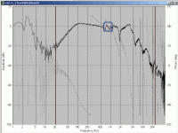
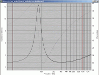
the nearfield and impedance measurements below show an anomaly which I suspect is reflection off the brace I mentioned. It was actually 32mm square not 25mm square as I previously posted. The anomaly disapeared if measured without the brace (on both the FR and impedance plots).
I pulled these images from an old thread, I don't have access to the original measurements at the moment. The circled anomaly was only present when the brace was in place. The scale is not very good unfortunately so it is a bit hard to tell how many db the difference is, but it is quite low and quite possibly would not be audible. However for a purist like me I'd rather not have the anomaly if It can be avoided. In this case the brace was not strictly needed, so I did without it. Obviously as with everything there are tradeoffs. If the brace removed a 6db resonance but introduced a 2db relflection anomaly then you would probably take the lesser of two evils
I recall from Joe D'appolito's "testing loudspeakers", a number of the examples he gives are of comercial products where he was asked to look at problems, and in a number of cases there were quite severe anomalies which were attributed to improper bracing. From memory I think these were where panels (with holes cut in them) were used as the braces.
I suspect also that the size of such anomalies will vary greatly depending on the construction of the drivers which are being used.
Tony.
Attachments
Hi , I just had a debate with my friend about bracing a speaker box.
He says that the minimum amount of bracing ( like 1 cross brace at the middle ) is enough , and that adding extra bracing would color the sound because the air is moving in many random directions and reflect off the braces .
While I said that the more bracing the better ( like B&W matrix method ... magico mini bracing method ... ) to achive zero panel resonance .
So what do you think ?
How about something like this for bracing overkill :
An externally hosted image should be here but it was not working when we last tested it.
..it's overkill (but there are still room for improvements).
Basically 2 "dowel's" for cross-bracing on the side panels are all that's warranted - however they should be "staggered" or more "randomized". They should be *closer* to the center of the panel.
You should NOT connect the rear panel to the front. Doing that just offers minor transmission back to the baffle/front panel. If you want to damp the rear panel then consider another means, though frankly I think it's largely unnecessary (i.e. it's facing the rear, the panel is fairly small and damped on all edges, etc..).
Now what is important that's missing?
1. Interior chamfer for the midbass driver.
2. Increased rigidity for front baffle (i.e. cement or damped steel plate).
3. Over-all weight. Presumably this is a stand-mount design, consider attaching a cable to the bottom panel with a "dangling" weight (rather like the swinging weight on a grandfather clock). (..the weight should be at least as heavy as the total loudspeaker without the weight.) Spikes turned UP FROM THE STAND (or pointed up) to the bottom panel (with metal coupling "discs" between the spike and panel).
4. IF you add an interior fiber - make sure it is at least an inch away from the walls (all interior panels), and at least 2 inches from the driver - usually by means of lossy suspension on the interior. Personally I'd ONLY hang about an inch-thick sheet of fiber about an inch and a half away from the interior of the rear panel. (..fiber sheet similar in size to the rear panel minus an inch plus on all 4 edges.) You can also "wrap" the cross-brace dowels in about an inch of fiber as well, but keep the dowels fairly small in diameter, and again - keep the fiber an inch or more OFF of the interior side panels.
Last edited:
... It was actually 32mm square not 25mm square as I previously posted. The anomaly disapeared if measured without the brace (on both the FR and impedance plots).
Hi Wintermute, thanks for your answer; I have to say that I do regard such an anomaly as not related to backwave energy because when we look at this phenomenon through the wave propagation laws the possibility that enough energy due to the area of the brace returns to the cone and disturbs it is very low...Think about the total energy coming from the cone and its propagation axe: a very few % meet the brace without being diffracted.
This being said I don't know what could be the real explanation of such an anomaly except that I would lean towards a panel resonance due to the brace?!...
gedlee -
I no longer have the data to show, it was years ago and done one the fly. Maybe something special in the instance I tested, but several cross braces front to back did almost nothing I could see, but subsequently adding surface braces made an easily measureable difference in the peaks picked up by an accelerometer. I interpreted it as the difference between coupling two resonators with the same resonant frequency together, which I'd expect to do little; and coupling it to a stiff ground point to raise and dampen the resonant frequency,
Next time I build a cabinet, I'll try it again and save data.
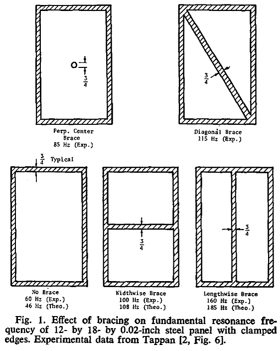
And the cross-brace (as shown) is the least effective of braces that cross across the cabinet to the other side. Higher panel resonance is better.
dave
Apples to apples ... if you use the same quantity of material as is for diagonal/widthwise/lenghtwise brace for perpendicular the results will be reversed.
gedlee -
I no longer have the data to show, it was years ago and done one the fly. Maybe something special in the instance I tested, but several cross braces front to back did almost nothing I could see, but subsequently adding surface braces made an easily measureable difference in the peaks picked up by an accelerometer. I interpreted it as the difference between coupling two resonators with the same resonant frequency together, which I'd expect to do little; and coupling it to a stiff ground point to raise and dampen the resonant frequency,
Next time I build a cabinet, I'll try it again and save data.
Front to back bracing would not do much, thats not "cross" bracing. You need to add a side-to-side brace as well. In other words a "cross" ("cross" bracing not "across" bracing), front-to-back rigidly attached to a side-to-side. This basically fixes the points of attachment, i.e. "grounds" them. If only front-to-back is used then the brace itself can still move to and fro and no real stiffening is achieved. So the mystery is solved!
Certainly it's better than none. I rather like surface-gluing small pieces of wood to the inside of the cab, in addition to a bracing scheme proper. You not add local stiffness, but you introduce some randomization to the internal acoustic environment. Great way to use up scraps.
- Status
- This old topic is closed. If you want to reopen this topic, contact a moderator using the "Report Post" button.
- Home
- Loudspeakers
- Multi-Way
- Bracing overkill yay or nay ?


