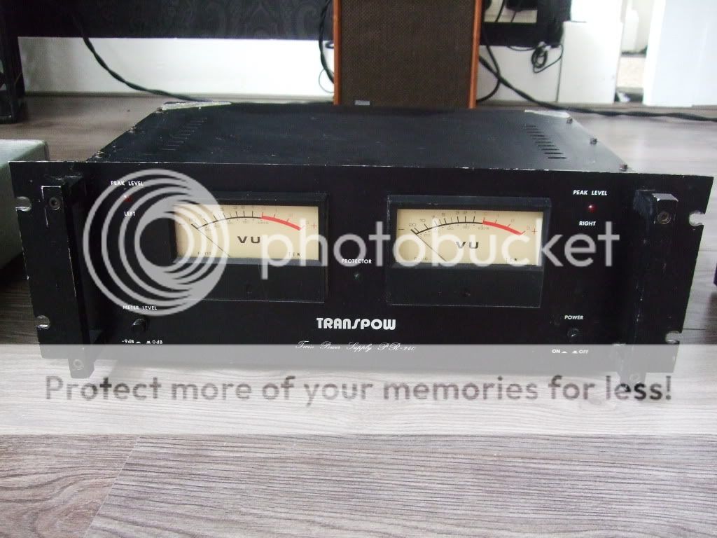
Transpow PR-240..
Bought one of these amps a couple of months ago.
I'd like to (know if it's worthwhile to) repair this little beast. I'll find out soon how cleaning affects the sound anyway.")
Unafortunately I cannot find anything about it. I'd greatly appreciate it if anyone can help me to find info. I suspect it might be a kit build?
Bought one of these amps a couple of months ago.
I'd like to (know if it's worthwhile to) repair this little beast. I'll find out soon how cleaning affects the sound anyway.
Unafortunately I cannot find anything about it. I'd greatly appreciate it if anyone can help me to find info. I suspect it might be a kit build?
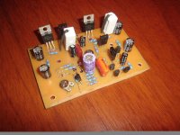
Hi! this is my first post in DIY Audio!
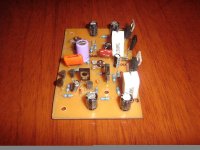
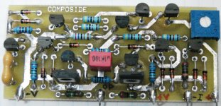
Here I share my first project, it's MOSFET amplifier (1 channel shown in the photo), supply is +/- 30 VDC, power output about 30W at 8 ohm (that's what I'm using now).
I made two of these stages, the transformer is rated at 100VA, the capacitors values of the power supply are 4700uF (I will add more caps to it soon).
I made it few months ago and it works pretty fine (begginners luck?) jaja. This stage is from PCP Audio (spanish web if you look for it).
I also made a 24db/octave crossover (from ESP Audio) and the voltage regulator from the same author (yes, I'm thinking about bi-amplifing). I tested them (not for a long time, as I don't have another amp yet) and worked well.
Now I'm going for the woofer amp, I decided S-Sub from PCP Audio too.
The speakers consist on 8" woofer, 5" mid and 1" dome tweeter.
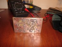
I Didn't make a chassis for it yet... because I haven't decided what I'm going to include inside it yet...
So I still experimenting and enjoying!
Salute!
Here I share my first project, it's MOSFET amplifier (1 channel shown in the photo), supply is +/- 30 VDC, power output about 30W at 8 ohm (that's what I'm using now).
I made two of these stages, the transformer is rated at 100VA, the capacitors values of the power supply are 4700uF (I will add more caps to it soon).
I made it few months ago and it works pretty fine (begginners luck?) jaja. This stage is from PCP Audio (spanish web if you look for it).
I also made a 24db/octave crossover (from ESP Audio) and the voltage regulator from the same author (yes, I'm thinking about bi-amplifing). I tested them (not for a long time, as I don't have another amp yet) and worked well.
Now I'm going for the woofer amp, I decided S-Sub from PCP Audio too.
The speakers consist on 8" woofer, 5" mid and 1" dome tweeter.
I Didn't make a chassis for it yet... because I haven't decided what I'm going to include inside it yet...
So I still experimenting and enjoying!
Salute!
Attachments
Hi! this is my first post in DIY Audio!
Here I share my first project, it's MOSFET amplifier (1 channel shown in the photo), supply is +/- 30 VDC, power output about 30W at 8 ohm (that's what I'm using now).
I made two of these stages, the transformer is rated at 100VA, the capacitors values of the power supply are 4700uF (I will add more caps to it soon).
I made it few months ago and it works pretty fine (begginners luck?) jaja. This stage is from PCP Audio (spanish web if you look for it).
I also made a 24db/octave crossover (from ESP Audio) and the voltage regulator from the same author (yes, I'm thinking about bi-amplifing). I tested them (not for a long time, as I don't have another amp yet) and worked well.
Now I'm going for the woofer amp, I decided S-Sub from PCP Audio too.
The speakers consist on 8" woofer, 5" mid and 1" dome tweeter.
I Didn't make a chassis for it yet... because I haven't decided what I'm going to include inside it yet...
So I still experimenting and enjoying!
Salute!
Hi Fedess, congrats and welcome
I like the build of yours, i were using google translate to read the spanish ( thanks to google translate for this fine tool ). I find PCP's site very informative, it seems to be the right place for people, who are new into DIY projects, all in all a great site.
The project of yours: DIY AMP PUBLIC - PCPfiles en www.pcpaudio.com
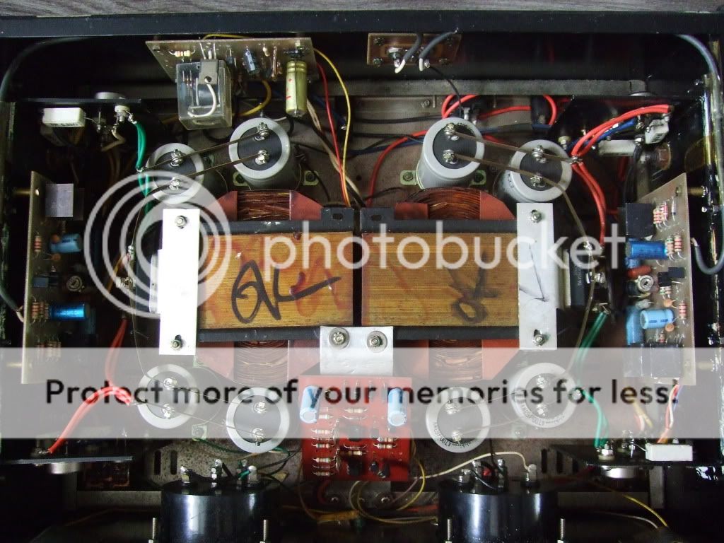
Voltcontrol: " I'd like to (know if it's worthwhile to) repair this little beast. ..."
ostripper: " ... Looks like a high current dual 55-0-55 Vdc setup. good for a 120W amp. "
Here is what I would do (and have done): Keep all the cool hardware, trannies, caps, gauges, switches ... and strip the old audio circuits out and add modular amplifiers ... Example: HPA-nxV200 180 watt MOSFET Audio Amplifier Module ... or ...
Hi, thanks everybody!
KrammeAcoustics: Thank you! I can help with some translation from spanish to english if you find something interesting
Mooly: thank you! what do you mean with correcting grounding?
regiregi22: It sounds much clearer than a commercial (gainclone) soundsytem!! The difference is very noticeable. =) The response is flatter than commercial but it still needs some eq (or maybe my speakers need it...!)
Thnx Ostripper, do you have an axample of a nice design?
I was thinking in the lines of a dual mono Firstwatt F5 diy.
But honestly, I don't know enough about electronics to develop that (yet..).
I don't do those 25w amps , for a 53-0-53VDC setup like yours an AX1.0 with a PB-120 powerboard will do fine. (attached below) Dual mono with these would be sweet.
Just a tweaked Doug Self blameless. At a hundred mA bias it is in class A anyways, (firstwatt??) with .0002%THD.
With the PB120 (120w powerboard) or PB-200 you can add any voltage board you like :
AX1 - Blameless
BX1 - RCA bootstrap amp (like aksa55)
CX1.1 - balanced VAS (symasym style) my favorite.
no DX1 - copyright issue.
EX1 - Complimentary balanced amp (leach style)
FX1 - A Harmon-Kardon clone , very highly acclaimed.
What is nice all the voltage boards will work with any of the powerboards seamlessly. If you want to try something new , plug it in.
OS
Attachments
1600watt amplifier module
1600 watt MOSFET amplifier module.
1600 watt MOSFET amplifier module.
An externally hosted image should be here but it was not working when we last tested it.
1600 watt MOSFET amplifier module.
An externally hosted image should be here but it was not working when we last tested it.
1600 watts is a lot but, is it 1600 watts at 1 ohm and peak power?
1600 watts is a lot but, is it 1600 watts at 1 ohm and peak power?
2 ohms at 1600 watts peak with +/- 63 volt rails.
that's cheating. Same sin as the retailers who try to con their customers.2 ohms at 1600 watts peak with +/- 63 volt rails.
800W into 2r0 sinewave power with ?% duty cycle.
Who cares about...
This is the last discrete operational amplifier that i designed 6 months ago. The reason was to make something that can surpass the problem of performance variation according to the level of power supply. An annoying problem that i had encountered with Burson's discrete. This module, it has the same performance with any symmetrical power supply from +/-12V up to +/-30V. It is implemented at whole with BJTs (BC550C - BC560C, MJE172 - MJE182) but it has a very good bandwidth, up to 650KHz. Connected in non-inverting mode for Av=2, with Zin=5KΩ and RL=500Ω, it has a rise time of 600nsec thus a bandwidth = 0.34 / 600nsec = 560KHz. Later i decided to make a further improvement. To eliminate the need for voltage regulators in power supply. I removed any current mirror, and i added constant current sources in all stages. The result is very good. This module supplied with +/-30Vdc from unregulated power supply it presents in output a ripple noise of just 50μV. The use of voltage regulators is only an option. During a test with voltage regulators with BJTs connected in common base mode in their outputs, the ripple noise wasn't reduced further. Later i started a new drawing with SMD parts to reduce the PCB size as much as possible. I have finished the new SMD PCB but i had never the chance or the mood to assemble it ... six months ago.
This is the last discrete operational amplifier that i designed 6 months ago. The reason was to make something that can surpass the problem of performance variation according to the level of power supply. An annoying problem that i had encountered with Burson's discrete. This module, it has the same performance with any symmetrical power supply from +/-12V up to +/-30V. It is implemented at whole with BJTs (BC550C - BC560C, MJE172 - MJE182) but it has a very good bandwidth, up to 650KHz. Connected in non-inverting mode for Av=2, with Zin=5KΩ and RL=500Ω, it has a rise time of 600nsec thus a bandwidth = 0.34 / 600nsec = 560KHz. Later i decided to make a further improvement. To eliminate the need for voltage regulators in power supply. I removed any current mirror, and i added constant current sources in all stages. The result is very good. This module supplied with +/-30Vdc from unregulated power supply it presents in output a ripple noise of just 50μV. The use of voltage regulators is only an option. During a test with voltage regulators with BJTs connected in common base mode in their outputs, the ripple noise wasn't reduced further. Later i started a new drawing with SMD parts to reduce the PCB size as much as possible. I have finished the new SMD PCB but i had never the chance or the mood to assemble it ... six months ago.
Attachments
that's cheating. Same sin as the retailers who try to con their customers.
800W into 2r0 sinewave power with ?% duty cycle.
Its not a sin at all thats the standard way of describing an amps power.
Its 1600watt peak and 1100WRMS.
- Home
- Amplifiers
- Solid State
- Post your Solid State pics here