Excellent explanationOk I have heard of short posts. But this has to be the shortest of them all
BP1Fanatic??
Mark
")
I've seen plenty of horns on here and other audio forums where the throat chamber average cross sectional area is less than Sd.Why don't new horns have little holes or slots for the drivers to face, not their full diameter, like the old horns?
GoodSoundClub - Romy the Cat's Audio Site - The pocket size 20Hz tapped horn.
Free Speaker Plans - Free Speaker Plans ? View topic - Folded 1x15 Horn
http://www.worldconspiracy.org/speakers/TH-Mini-Clone.png
Review
Somewhat relevant to this thread and by way of shameless promotion, here's a writeup with some Trio12 content.
Creative Sound Trio12 Reworking surplus cabinets to create a new subwoofer. Article By Jeff Poth
Somewhat relevant to this thread and by way of shameless promotion, here's a writeup with some Trio12 content.
Creative Sound Trio12 Reworking surplus cabinets to create a new subwoofer. Article By Jeff Poth
BP1Fanatic - thanks. Interesting to read about THs and small mouths.
I can't shake the impression they are transmission line enclosures perhaps needlessly shaped somewhat like horns and with nice performance within two bass octaves. Given the support they have around here, I'll continue to think about their benefits.
Interesting to read about "2007 NYC sub shoot out" - any links? Any toe-to-toe comparisons with, say, Big Folded Corner Horn?
shameless promotion, here's a writeup with some Trio12 content.
Hey I read this a while back. And it is well written. Promote away!
As for small mouths in horns they can work well. It is a carefull balalnce of size and horn path length that can get you decent results. Also the ability to take what a simulator gives you and throw in experience as to what really will work. A bit oh elbow grease and you get something worth while. A ruller flat response is there for text books and fairy tales. Flat enough is what we hear in real life.
Mark
I can't shake the impression they are transmission line enclosures perhaps needlessly shaped somewhat like horns and with nice performance within two bass octaves.
Some folks maintain that a horn is just an expanding TL. The expansion makes a significant difference compared to a tapped pipe (TL), but the trade-off is it's much bigger. Note too that more than two usable octaves is available with the right driver.
Think of it this way, an ideal compression horn will be very long due to a very slowly expanding hyperbolic T = ~0.5 depending on driver specs, so if you slice a portion of it off beginning at the throat you find that for all intent and purpose it's a conic expansion to a small mouth (TL), ergo no bass and considerable ripple, but if you tap into it at the right place it will fill in/flatten out in the LF and the acoustic loading will considerably dampen some of its HF ripple as well as increase driver loading per Watt.
That said, the majority of DIY THs I've posted or seen done by others are simply HF tapped TLs (drivers near/at the mouth). They work quite well since they are just acoustically damped pipe horns (TLs) and easy to make.
GM
I was not trying to promote anything. I was giving bentoronto examples of "new horns have little holes or slots for the drivers to face, not their full diameter," to support my statement. All I did was Google Images "horn compression chamber."Somewhat relevant to this thread and by way of shameless promotion
No problem guy!BP1Fanatic - thanks. Interesting to read about THs and small mouths.
I posted this a while back on another forum. Diymobileaudio.
It describes fairly coherently what horns do best:
From what I have come to believe in building and designing horns this is my theory in a nutshell ( albeit a rather big nut shell ).
Horns can massage more molecules of air per given movement of the cone than any other box configuration that I know of. Because they can do that they are more efficient than any driver directly radiating into a room or space. Because they do more with less they can also when properly designed do it it much less distortion. You just have to look at the cones in a horn when it is pumping out crazy volume and the cones are barely moving.
The explanation for this effect that I have read that makes the most sense and that I can attest to from my own observation is that the molecules of air that get vibrated or excited by the cone movement want to dissipate their little bit of energy.( No I can't see molecules of air
We know from basic physics that every object acted upon by an outside force wants to dissipate it's energy and return to a state of rest. So all the excited molecules of air within that horn structure are a captive system that has a given mass of air within it. That given mass of air when excited by a driver wants to get back to it's resting point. So all that energy gets shot out of the mouth of the horn and it dissipates into the room. But the efficiency lies in the trick that a great big amount of trapped air within that horn has been driven into vibration by that loudspeaker cone. That is why the horn is more efficient. No directly radiating cone could ever push around as much air . That is also why when you simulate horns you usually find that the larger the volume of the horn the greater it's efficiency. It really Sucks because everyone wants a small horn that acts like a big horn. But a big horn with a few watts can blow away any normal box be it sealed or vented with much less distortion in the sound than any normal radiating box with even kilowatts of power behind it.
I'll add this bit:
A large horn has the exciteable air mass within it that no other driver/box sytem can compete with. A tranmission line is not really a horn in that it changes the acoustical impedance of the driver/ room interaction to the same degree. As GM pointed out almost all the tapped horns are quater wavelength resonators that have there length tapped at some point to approximate what we see in Danley's designs. But few have any appreciable gain in the efficiency of the drivers base level SPL / watt. Danley's do.
I know through private correspondence that GM and I have designed true tapped horns. But out of respect for the guy who needs to make a living from them I won't post any designs. I say this because a lot of effort is required to get a driver / box design to the point that Mr. Danley has worked to. I'm in awe of the idea. To create a horn that is essentially a horn bandpass hybrid that really works is truly a ingenious feat of true engineering. There may be prior art to the effect that it has been proposed before. But that does not mean that anyone has actually gotten the things to work as well as he has.
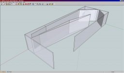
So failing a tapped horn that would only be about 18% smaller and a couple db less efficient I give this design as a starting point for the bass starved amongst us. A good friend did this rendering for me. It gives a great representation as to what is inside.
Now I have a question or two regarding preferend building materials.
5' x 5' baltic birch?
4 x 8 baltic birch?
4 x 8 structural sheeting?
What is readily available? I'm a cabinet maker. I can get almost anything. But what is generally available is more important.
Or should I provide cut sheets for both sizes and do it that way?
Mark
It describes fairly coherently what horns do best:
From what I have come to believe in building and designing horns this is my theory in a nutshell ( albeit a rather big nut shell ).
Horns can massage more molecules of air per given movement of the cone than any other box configuration that I know of. Because they can do that they are more efficient than any driver directly radiating into a room or space. Because they do more with less they can also when properly designed do it it much less distortion. You just have to look at the cones in a horn when it is pumping out crazy volume and the cones are barely moving.
The explanation for this effect that I have read that makes the most sense and that I can attest to from my own observation is that the molecules of air that get vibrated or excited by the cone movement want to dissipate their little bit of energy.( No I can't see molecules of air
An externally hosted image should be here but it was not working when we last tested it.
) That is true with any driver radiating into any space. In a horn they have to do that with a very controlled amount of air molecules. Less close to the driver as the horn area is smaller there. These little air molecules are most energetic when closest to the driver and as they are pushed along because they are being corralled and herded by the horn structure from a very confined space to a more open space. The originally excited molecules of air excite more molecules of air on their way out of the horn. They loose a bit of energy from each exchange of energy molecule to molecule. But the greater the number of molecules that are excited to a higher energy greater the potential sound pressure level at the mouth of the horn. We know from basic physics that every object acted upon by an outside force wants to dissipate it's energy and return to a state of rest. So all the excited molecules of air within that horn structure are a captive system that has a given mass of air within it. That given mass of air when excited by a driver wants to get back to it's resting point. So all that energy gets shot out of the mouth of the horn and it dissipates into the room. But the efficiency lies in the trick that a great big amount of trapped air within that horn has been driven into vibration by that loudspeaker cone. That is why the horn is more efficient. No directly radiating cone could ever push around as much air . That is also why when you simulate horns you usually find that the larger the volume of the horn the greater it's efficiency. It really Sucks because everyone wants a small horn that acts like a big horn. But a big horn with a few watts can blow away any normal box be it sealed or vented with much less distortion in the sound than any normal radiating box with even kilowatts of power behind it.
I'll add this bit:
A large horn has the exciteable air mass within it that no other driver/box sytem can compete with. A tranmission line is not really a horn in that it changes the acoustical impedance of the driver/ room interaction to the same degree. As GM pointed out almost all the tapped horns are quater wavelength resonators that have there length tapped at some point to approximate what we see in Danley's designs. But few have any appreciable gain in the efficiency of the drivers base level SPL / watt. Danley's do.
I know through private correspondence that GM and I have designed true tapped horns. But out of respect for the guy who needs to make a living from them I won't post any designs. I say this because a lot of effort is required to get a driver / box design to the point that Mr. Danley has worked to. I'm in awe of the idea. To create a horn that is essentially a horn bandpass hybrid that really works is truly a ingenious feat of true engineering. There may be prior art to the effect that it has been proposed before. But that does not mean that anyone has actually gotten the things to work as well as he has.
So failing a tapped horn that would only be about 18% smaller and a couple db less efficient I give this design as a starting point for the bass starved amongst us. A good friend did this rendering for me. It gives a great representation as to what is inside.
Now I have a question or two regarding preferend building materials.
5' x 5' baltic birch?
4 x 8 baltic birch?
4 x 8 structural sheeting?
What is readily available? I'm a cabinet maker. I can get almost anything. But what is generally available is more important.
Or should I provide cut sheets for both sizes and do it that way?
Mark
Attachments
I have noticed in Hornresp similations that better performance can be had with "bandpass hybrid" compression chambers in TH's.I know through private correspondence that GM and I have designed true tapped horns. But out of respect for the guy who needs to make a living from them I won't post any designs. I say this because a lot of effort is required to get a driver / box design to the point that Mr. Danley has worked to. I'm in awe of the idea. To create a horn that is essentially a horn bandpass hybrid that really works is truly a ingenious feat of true engineering. There may be prior art to the effect that it has been proposed before. But that does not mean that anyone has actually gotten the things to work as well as he has.
(WO/2007/109075) SOUND REPRODUCTION WITH IMPROVED LOW FREQUENCY CHARACTERISTICS
An externally hosted image should be here but it was not working when we last tested it.
Whenever I see that TH/horn picture, I can't help but think of the Karlson enclosure, called "multiresonant" by Kipsch.
That ancient TH picture does capture the concept well, from what little I know. But trafficking in resonances (or in the case of THs, of tuned reinforcement) of any sort doesn't seem beneficial except maybe in the degenerative case when the ear just isn't discriminating much and the Q of the reinforcement about as wide as the passband.
I thought the goal was to be rid of resonances not to buy into them?
Can a TH sound great? The evidence seems to be "yes." So as a practical solution, might make sense for the last octave and if carefully designed for direct radiation, an octave above.
Mark - don't know if my metaphor is better than yours but a true horn is an impedance-matching (air impedance) transformer vis a vis the outlet; the air at the mouth is "thicker" so that hunk of cardboard (supid idea?) can push better against it. At higher frequencies, the problems with horns outweigh the impedance-matching benefits.
Last edited:
The Karlson looks like a Series Tuned Dual Reflex
Bandpass Enclosure.

Bandpass Enclosure.
An externally hosted image should be here but it was not working when we last tested it.
Right. Fair analysis, as far as I know.
In both TH and Karlson, you have upper-band direct radiation (unfortunately impaired by the needs of the reverse-cone treatment). But the reverse-cone sound is used constructively albeit by trafficking either in resonances or phase.
That's not materially different than bass-reflex (some good examples have ben produced, I am sure) but it is different than sealed, "infinite"or dipole, or horn loading.
All these systems have nice implementations. Perhaps those who like sanitary/elegant solutions, like me, avoid messing with tuning as a means of augmenting sound. Those who are results-oriented, might well love THs.
Have I summarized in a way others can agree with?
(Watch for my post on the Samba Squad street band, 119 dBC, fast, peak.)
Last edited:
The Karlson looks like a Series Tuned Dual Reflex
Bandpass Enclosure.
An externally hosted image should be here but it was not working when we last tested it.
I'd like to see an impedance response graph for one of those Karlsons. If it's a series-tuned BP, the upper resonance frequency is likely to be quite high.
I can't find the Z plot for the little (17.25"x11.75"x9.375") Karlson 8 shown but here's some other I've taken - done right its a great design
an 18" driver sealed rear chamber "klam" I made
1954 Karlson 12 loaded with Fe206EN and W8-1772
Karlsonette loaded with WBAL "BetsyK"
1957 style Karlson 12 loaded with Beta 12LTA - vents sealed with tape
impedance of 42" x22.5" x 16" coupler with Electar/Eminence 18" speaker
25.5" high K12 per July 1958 Popular Mechanics article - 3rd Z peak 235Hz
27" high Acoustic Control 115BK coupler - VBf ~0.9 cubic foot, 3rd Z 224.6Hz
32" tall 21.25" wide by 16" deep coupler-- total bulk 6.3 cubic feet - coupler volume ~1.6 cubic foot - 3rd Z peak 195Hz
same box as above but add a 20 liter cavity to the front chamber via 2.4" x 19.6" slot
effect upon response outdoors of adding the 20 liter cavity
same box but add 45 liter cavity - note drop in 3rd Z peak's placement
bandpass simulation of this condition
inroom effect of adding 45 liter cavity -
it either detuned like a bandpass or the added cavity was resonating and causing the 80Hz drop
Stock K15 - that 155Hz Z peak remains if its tuned low
8 cubic foot bulk 32" tall coupler - why does its 3rd Z peak come in higher than K15?
an 18" driver sealed rear chamber "klam" I made
An externally hosted image should be here but it was not working when we last tested it.
1954 Karlson 12 loaded with Fe206EN and W8-1772
An externally hosted image should be here but it was not working when we last tested it.
Karlsonette loaded with WBAL "BetsyK"
An externally hosted image should be here but it was not working when we last tested it.
1957 style Karlson 12 loaded with Beta 12LTA - vents sealed with tape
An externally hosted image should be here but it was not working when we last tested it.
impedance of 42" x22.5" x 16" coupler with Electar/Eminence 18" speaker
An externally hosted image should be here but it was not working when we last tested it.
25.5" high K12 per July 1958 Popular Mechanics article - 3rd Z peak 235Hz
An externally hosted image should be here but it was not working when we last tested it.
27" high Acoustic Control 115BK coupler - VBf ~0.9 cubic foot, 3rd Z 224.6Hz
An externally hosted image should be here but it was not working when we last tested it.
32" tall 21.25" wide by 16" deep coupler-- total bulk 6.3 cubic feet - coupler volume ~1.6 cubic foot - 3rd Z peak 195Hz
An externally hosted image should be here but it was not working when we last tested it.
same box as above but add a 20 liter cavity to the front chamber via 2.4" x 19.6" slot
An externally hosted image should be here but it was not working when we last tested it.
effect upon response outdoors of adding the 20 liter cavity
An externally hosted image should be here but it was not working when we last tested it.
same box but add 45 liter cavity - note drop in 3rd Z peak's placement
An externally hosted image should be here but it was not working when we last tested it.
bandpass simulation of this condition
An externally hosted image should be here but it was not working when we last tested it.
inroom effect of adding 45 liter cavity -
it either detuned like a bandpass or the added cavity was resonating and causing the 80Hz drop
An externally hosted image should be here but it was not working when we last tested it.
Stock K15 - that 155Hz Z peak remains if its tuned low
An externally hosted image should be here but it was not working when we last tested it.
8 cubic foot bulk 32" tall coupler - why does its 3rd Z peak come in higher than K15?
An externally hosted image should be here but it was not working when we last tested it.
I can't find the Z plot for the little (17.25"x11.75"x9.375") Karlson 8 shown but here's some other I've taken - done right its a great design
Whoa, that's a whole lot of Karlsons...
Are you finding that you're getting good results (impedance, phase) trying to emulate them as 6th order BP boxes?
hi Brian - -BP sim for karlson is better than nothing - - -getting a baffle angle in a sweet spot to prevent a big hole seems to be just a guess - aperture area, shape and starting gap control their sound and maybe system damping. it would be nice if someone works out a flexible and simple aKaBaK model or a way to fudge in hornresp.
How about modeling it as a Series Tuned Vented FLH with
a positive taper from S1 (3.25 x 11.75) to S2 (4.375 x 11.75),
a negative taper from S2 to S3 (the area of an exponential triangle),
or
S1 (0.01) to S2 (4.375 x 11.75),
a negative taper from S2 to S3 (the area of an exponential triangle),
and a vent = Ap1 [3 x (0.625 x 7.4375)] & Lpt (0.75) in Hornresp?
Have fun calculating the L1 & L2 lengths and the rear chamber volume
An externally hosted image should be here but it was not working when we last tested it.
- Status
- This old topic is closed. If you want to reopen this topic, contact a moderator using the "Report Post" button.
- Home
- Loudspeakers
- Subwoofers
- TRIO 12 Front loaded Horn Subwoofer