Hello JCX
I certainly agree with that. Sadly, it seems that much of the DIY membership has little scientific interest nor the discipline to formally explore audio electronics.
Interests seem to lie elsewhere in the snippets of info about other people's work
It also seems that its ok for a series of seemingly respectable qualified audio technology guys to "bomb" and even troll threads that aren't producing or using correct principles to arrive at designs that they feel should be competent and with recognizeable technical merit. Regardless of the standard of thread activity, the rules don't say anything about such a requirement for projects or discussions.
It would seem then that both, even all flavours of audio interest should be accomodated here. It is DIY. My attitude would be to invite rather than incite debate so that others who do have a technical contribution to make, will feel welcome to do so. Unfortunately, that seems difficult to do with personalities becoming such a confounded part of otherwise informative debate here. You may gather that I see no value in debate predicated on ones prowess as an intellectual or social bully.
Actually, I don't think that there's much diiference in the potential of most threads to reach great heights. The contributors make the quality and good science. If the so educated will not participate and reveal the truth but conceal it behind commercial interest or apathy then it just can't and doesn't happen. On the other hand, opinions, good and bad, subjective or objective, spark objection or enthusiasm and the the search for hard evidence. That's got to be good but only as long as someone has the determination to finish and prove it.
If you think about it, who in the scientific community would want to, less be seen to, revisit old-tech caps in the amp output? Only DIYs with a bent for quirky audio is who. Some of 'em seem pretty enthusiastic about it though.
Since Gordy has drawn his own conclusions but there are still questions that haven't been discussed, would others like to suggest whether we should continue with caps in the output?
D. Self has measurements of amplifiers with output cap in his new book. The conclusion was that caps distort when a voltage develops over them. To prove the concept he used a 100.000 uF at the output and distortion in the bass disappeared. If that is economical is another question. How about bringing the output cap in a feedback loop ?
subjective vs objective data
Pardon me, but I helped bring up this problem of using output capacitors to save $600 speakers from DC in response the the thread http://www.diyaudio.com/forums/solid-state/166667-power-amplifier-blew-took-speaker.html where an inexpensive split supply amp destroyed someone's speakers. As a troller of charity resale shops and used musical instrument stores, I don't find this problem to be unusual. I made the rude comment that the single supply amp with output capacitor, the ST120, rarely burned up speakers. Mooly invited me to put a capacitor in series with the output of a split supply amp. I have done so. The results are not subjectively as good as the ST120 with D Joffe mod, or as good as the split supply amp without a capacitor. In fact on my speaker demo records cited previously, I can't tell the differnce between the op amp input (no input capacitor) split supply output (no output capacitor) CS800S, and the St120 with output capacitor and a much reviled 4.7 uf ceramic input capacitor. My only instrumentation available at this time is a scope, and my construction of a square wave generator is waiting my finding of the 1974 Signetics book with the 555 ap note to enable me to convert a monostable 555 board into an astable 555 board. I am not adverse to science, but it is high summer and I made significant progress on non-electronic projects this week requiring no rain. So I expect to post square wave results, but not instantly. Meanwhile, MOS57, the way you tell the output capacitor from the power supply capacitor on a split supply amp, is that it is the one outside the box. Also, the power supply capacitor normally stays in the range of a few volt to supply rail, whereas the output capacitor on a split supply amp crosses zero every electrical cycle, where interesting chemical events occur on an electrolytic capacitor. Thanks for your interest of some knowledgeable people.
Pardon me, but I helped bring up this problem of using output capacitors to save $600 speakers from DC in response the the thread http://www.diyaudio.com/forums/solid-state/166667-power-amplifier-blew-took-speaker.html where an inexpensive split supply amp destroyed someone's speakers. As a troller of charity resale shops and used musical instrument stores, I don't find this problem to be unusual. I made the rude comment that the single supply amp with output capacitor, the ST120, rarely burned up speakers. Mooly invited me to put a capacitor in series with the output of a split supply amp. I have done so. The results are not subjectively as good as the ST120 with D Joffe mod, or as good as the split supply amp without a capacitor. In fact on my speaker demo records cited previously, I can't tell the differnce between the op amp input (no input capacitor) split supply output (no output capacitor) CS800S, and the St120 with output capacitor and a much reviled 4.7 uf ceramic input capacitor. My only instrumentation available at this time is a scope, and my construction of a square wave generator is waiting my finding of the 1974 Signetics book with the 555 ap note to enable me to convert a monostable 555 board into an astable 555 board. I am not adverse to science, but it is high summer and I made significant progress on non-electronic projects this week requiring no rain. So I expect to post square wave results, but not instantly. Meanwhile, MOS57, the way you tell the output capacitor from the power supply capacitor on a split supply amp, is that it is the one outside the box. Also, the power supply capacitor normally stays in the range of a few volt to supply rail, whereas the output capacitor on a split supply amp crosses zero every electrical cycle, where interesting chemical events occur on an electrolytic capacitor. Thanks for your interest of some knowledgeable people.
Well, FWIW and since I'm awful at posting diagrams here you don't need to get too technical to turn 555 mono to astable.
Suggest removing all connections to p7.
Remove trigger input from p2 and join p2 to p6.
Add R between P6 and the output, p3.
C alone should already be at P6 to common ground.
F= .7/RC which is about as complex as I like to think about on Sunday afternoons.
for reference, p8+p4 go to Vcc, p1 ground, p5 .01 uf to ground - done.
It's quite a different setting and equipment that you have to most members, Indianajo, which makes your evaluations all the more interesting, thanks.
Hi Joachim, I was just looking at the beginning of the thread where Bob91343
nominated the addition of feedback around the cap. Including the DC error feedback from the OP would be an issue. Adding a DC servo may be obvious but I would hesitate to leave Global feedback in the care of an electro. Others might have done this or otherwise combined the cap error with GNF...
The output capacitor is only one of many other influence factors.
If there are two identical circuit amp topologies, one with symmetrical PS with DC coupled loudspeaker and Relais contact for DC protect for loudspeaker and an other with unsymmetrical PS and AC coupled loudspeaker (i. e. electrolytic cap in series without relais switch contact), both devices with top class devices in all respects and without design errors, the last delivers objective and subjective the best sonic results.
Additional advantages I have by the last AC coupling solution:
1) the NFB cap (for DC-gain = unity gain) can be also polarized type
2) no exact 0 V offset adjust (resp. perfect DC symmetric adjust) nessecary
3) no "0 volts" at both connectons by the NFB network
4) no DC-servo necessary
5) choise of the right capacity value (input cap, NFB cap and output cap - actually a crossover adjust for the smooth frequency response modelling) by the use of small, medium and large vented and closed loudspeaker cabinets (rule for lowest necessary acoustical measured f3: not lower than 20-22 Hz for the the largest enclosures).
6) No relais contact in series to the load (main advantage).
The disadvantages are only follow: twice of the DC voltage for the power supply cap and that one for the output and thus more expensive by the use of the same quality class.
By loads below 4 ohms (like Infinity Kappa or full range ribbon like Apogee) the cap value must be very very large arround 0,5-1F.
BTW - most people think, by symmetric PS and complete dc coupling (perhaps also the use of DC servo) there must be no caps in series to the signal. This isn't true, because the influence of the power supply caps is still very very large, independend of the circuit topology.
The reason therefore is the aera between the -3 db high pass frequency causes the whole capacity value of the power supply caps and the clean DC response condition (created through the connection of the mid-connection from the secundary windings).
By an other Thread here I have this descripted more exactly.
But I know, the most developers don't have my view of this because they think, through the DC coupling the influence of the ps caps are negible (the evidence therefore is simple; look at the quality standart to the caps in currently commercial home hifi amplifier products and compare it with vintage versions).
My opinion for the wrong thinking of the most engineers is the kind of schematic drawing. If one remove the GND/Earth symboles all and create normal connections, you will get complete other understanding and view.
I am thinking about where to connect the speaker negative wire in a single supply amp.
Either at the ground terminal at the main cap in supply or alternative at the bottom transistor ground connection?
If it is correct that on negative pulses the supply cap is disconnected the latter might be most optimal?
I don't see advantages, if you connect the neg speaker wire to the bottom transistor ground instead at the ground terminal from the main cap.
For me must go follow separately leads/wires to ground terminal from the main cap for ideal mass management:
- bottom power transistor ground (together with associated driver resistor)
- neg. speaker pole
- NFB-GND
- if current sources present, mass of ref. current resistors
- input resistor/capacitor (not directly, but about input connector/metal cabinet of the amp housing/enclosure)
All leads should be as short as possible, but on the other hand should not high-resistance areas to be close to lines with high pulse current (like e. g. the wire from power transistor GND to main cap).
BTW - cap is disconnected by negative pulses, if you work with sine wave signals. By normal music material there are no such situations.
Last edited:
I am only talking about the high current wiring from:
PSU Cap->Output transistor->Output terminal
As I understand, the best way will be to have seperate wires from PSU Cap to Output terminal and Output transistor?
yes.
Member
Joined 2009
Paid Member
I see tief', that we are on the same page with respect to the important role played by PSU capacitors. It's also important to remember that in amps with nfb the distortion produced by caps may or may not be partially compensated for. In the case of psu caps there is a good argument to support their influence being less because of this. For me it's 'clear' that the psu caps are in the signal path because....
and here I'm giving visibility of my personal approach to DIY audio that I haven't really shared before:
When looking at amplifier schematics I include the speaker and the psu. I then look at the schematic in terms of
a) CURRENT LOOPS - current always flows in loops, either directly through conductors or as displacement current through dielectrics. When I visualize current loops I see things more clearly. For example, I look to see what is actually in the path of the current that flows through the speaker and what is not. I see where dc current flows and where ac current flows. I see where large currents flow and where small currents flow. Generally, I view everything in terms of current flow. It also helps me think about wiring, because I don't like to see a wire on it's own anywhere, it implies that current flowing through this wire has a return path somewhere else along with a large area loop for magnetic pick up. I don't design pcb's with + and - rails diverging around the perimeter, I try to run them in parallel. It helps me think about current drive requirements (input impedance, output impedance) and many other things besides.
b) DIFFERENTIAL VOLTAGES - as a controlling element - I mean that I usually visualize voltages as being the control input to all the current flows. I view all active devices as voltage controlled devices, including BJTs. Voltage is always a differential, so I often visualize control voltages as differential, for BJTs I look at a schematic and see how a voltage is applied between base-emitter, and not as a voltage on a base with respect to gnd. I view gnd as an artificial creation, a reference point and it's use in schematics as a cause of wiring errors.
so there you have it !
for "in the signal path" to have meaning...
...some parts of the circuit have to be "not in the signal path"
I define "in the signal path" as having ~|1| small signal sensitivity to the Signal==amp output
again with the simple observation - typically you have Volts of 2x mains frequency ripple on psu caps - and we really, really don't want to listen to it - and we don't because any successful audio amp has large power supply rejection ratio = very low sensitivity to psu cap V
during those mS of 2x mains frequency charging current spikes in the psu caps you have a very good small signal connection to the mains - with popular toriodial xfmr the bandwidth can extend to 100 KHz
it really weakens the meaning of "in the signal path" if you include the whole world (or the electrical grid) where the effects on the amp output signal are fractions of a %
given that amps are designed so that we don't hear psu ripple - why persist with the unhelpful "psu caps are in the signal path" heuristic
just because the load current loop completes thru the psu cap doesn't cause the amp output Signal to be 1st order sensitive to psu cap V
Last edited:
Member
Joined 2009
Paid Member
why persist with the unhelpful "psu caps are in the signal path" heuristic
I will keep quiet then
")
your point of "following the current" is valuable and useful - I'm just worried that too many with less sophistication are mislead by loose definitions of "in the signal path"
while everything may affect the amp's output to some degree there is classically one "signal path" from input to output thru active devices and coupling components (sometimes the "path" has parallel branches for part of the way as in complementary diff pair/VAS)
The "signal path" is usefully defined as only the "path" where a inserted V (or parallel current source "on the signal path") gives a ~1:1 change in the output of the amp
as you mention V "signals" are always differential and may be referenced to gnd, or one or the other ps V at different points in the circuit - typically with high Z collector/drain "transferring" the signal as a current between different V refs - giving large isolation to the inter V ref difference V - like psu cap ripple V
for this discussion psu cap should not be equated with the series output coupling cap as "in the signal path" - they have vastly different effect on the output signal
clearly the output series cap is fully "in the signal path" and a any dV on it directly, in 1:1 ratio appears across the load
Member
Joined 2009
Paid Member
Fair enough - I'm count myself a newbie and it would be a case of the 'blind leading the blind' if I were to attempt to help others through my own strange thinking.
It's interesting, but I now realize that I'm using the words 'signal path' in more than one way - specifically I am using it differently than you are, and possibly differently than the 'norm' which is likely a bad thing on a Forum.
Anyhow, I'm thinking in terms of the current loop that flows through the speaker as the 'signal path' as far as the load is concerned - and this is not the same thing, as you point out, as the 'voltage' signal that travels from left to right across a schematic.
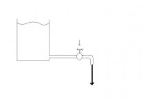
To make an hydraulic analogy:
The psu caps are the tank and the faucet the amplifier.
The waves at the surface does not affect so much what flows from the faucet. The faucet only controls the flow.
The quality of the tank is not very important.
The psu caps are the tank and the faucet the amplifier.
The waves at the surface does not affect so much what flows from the faucet. The faucet only controls the flow.
The quality of the tank is not very important.
Attachments
Last edited:
Member
Joined 2009
Paid Member
To make an hydraulic analogy:
The psu caps are the tank and the faucet the amplifier.
The waves at the surface does not affect so much what flows from the faucet. The faucet only controls the flow.
The quality of the tank is not very important.
the quality of the tank is important isn't it ? we are talking about distortion from capacitors which means that the capacitors impedance isn't a simple 1/C dependence - meaning the 'tank' affects the flow of water ??
To make an hydraulic analogy:
The psu caps are the tank and the faucet the amplifier.
The waves at the surface does not affect so much what flows from the faucet. The faucet only controls the flow.
The quality of the tank is not very important.
This visual comparison (hydraulic analogy - as you say) I hear from many manufacturers (respective their developers) that use cheap ps capacitors in their expensive audio amplifier devices. They justify the use of such low-cost capacitors very happy with it.
If there are amplifier circuit topologies with nearly perfect supply voltage suppression character - according opinion of the developers - brand and quality class of supply caps doesn't matter. But until this day nobody was able to demonstate me such amp resp. such circuit topology.
If you find such commercial power amps with a great amount of not used space in the height (there are enough brands and models), it is an easy task to replace such caps with computer grade versions. After done this and after soundcheck you will note, that the mentioned hydraulic analogy isn't right.
BTW: If the psu caps the tank, what are here the parasitic elements (inductors, dielectric and frequency dependend effects) ??
If there are only DC conditions (e. g. by chargers), then the visual comparison is reasonable (and the quality of the tank is indeed not very important).
check out also this thread, started by Mr. Nelson Pass:
http://www.diyaudio.com/forums/parts/151392-best-electrolytic-capacitors.html
Last edited:
...but the rest of us saw the ADVANTAGE of taking the output cap and putting it in the power supply, making a +/- supply. Then the 2 caps are in PARALLEL and do double duty, as the low Z series pass for the loudspeaker, and filtering the power supply ripple...
I am not sure I am understanding this correctly, but:
If the supply is changed from single to dual and the output cap is used in the "new" negative part of the supply, I would consider the two supply caps in series? And therefore doing "half-duty". In fact if the voltage over each cap is reduced by a factor 2, they might only be doing "quarter duty"?
Any thoughts about single supply only needing cap/4 compared to dual, but then needing higher voltage ratings?
- Status
- This old topic is closed. If you want to reopen this topic, contact a moderator using the "Report Post" button.
- Home
- Amplifiers
- Solid State
- Output capacitor: subjective and objective views?