Why exactly 50MHz?my target value is 50MHz
best
Wouldn't it be enough not to see over/down/shoots at the fronts and good square SPDIF waveform to consider fair impedance matching?
Is that waveform you showed the effect of using an RCA connector in a 50R SPDIF line (i.e., 50R characteristic impedance cable) with correct source and termination? If not, do you have such a waveform? Could you (or Guido) show the effect of an RCA connector on the analog output of a D/A as well, given an otherwise correct transmission path (i.e., 50R source, 50R cable, 50R termination)?
Or a 75R line. Bueller? Bueller?
what is sacred about 75 ohm
why not design for the RCA connector impedance
Because the redbook standard is set and adopted by the world. Unless you want to change it......
Some history:
In the standard making process, the RCA connector has been proposed by Sony. Their argument was that the average customer by then did not have "digital" cables at home, but plenty of average RCA based interlinks to use. Those cables in general are close to 75 ohm (the connector is not).
The RCA by the way became world standard because Morita adopted it in an attempt to enter the US with his Sony electronics, in which he succeeded.
There is not a single technical argument in favor of RCA connectors......
best
Last edited:
Why exactly 50MHz?
Wouldn't it be enough not to see over/down/shoots at the fronts and good square SPDIF waveform to consider fair impedance matching?
No, unfortunately not (the major question is: what is "good").
If the slope of the signal is not steep enough, induced noise at the receiver will increase the jitter.
Do yourself a favor, and build 2 constant impedance 75 ohm lowpass filters at say 10MHz and 5 MHz, and insert these respectively in the SPDIF signal of your chain. Notice what happens with the sound.
enjoy
@SY
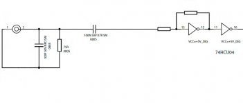
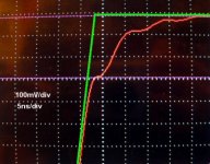
this dip down is effect of termination with 100 pF capacitor. 75R source, 75R BNC, 4 meter long 75R cable (+/-1.5R), 75R BNC input, termination with 75R + 100pF.
Cambridge Audio Dacmagic, if you want to knowInput section schematic attached
Yes, but my question was directed at the actual topic, not at adding capacitors- what is the effect of an RCA connector in a correct impedance line which is otherwise correctly driven and terminated? Do you or Guido or anyone else have transmitted waveforms or, better yet, analysis of the analog output of the D/A for that condition? Not speaker wires, not capacitors, not wrong impedances, but RCA plugs?
Because the redbook standard is set and adopted by the world. Unless you want to change it......
Some history:
In the standard making process, the RCA connector has been proposed by Sony. Their argument was that the average customer by then did not have "digital" cables at home, but plenty of average RCA based interlinks to use. Those cables in general are close to 75 ohm (the connector is not).
The RCA by the way became world standard because Morita adopted it in an attempt to enter the US with his Sony electronics, in which he succeeded.
There is not a single technical argument in favor of RCA connectors......
best
if you're designing RCA based equipment, it's not following the 'standard'

why not 'match' the impedance to the connector
Why exactly 50MHz?
Wouldn't it be enough not to see over/down/shoots at the fronts and good square SPDIF waveform to consider fair impedance matching?
Start with sine wave. Then convert sine wave to square wave.
Send square wave through transmission line. If you want square wave to remain square (with all harmonics), you will need some bandwith.
Required bandwith you can calculate yourself. First calculate S/PDIF frequency for 44.1 kHz material, LINK, then take into account all harmonics and you will have your required bandwith
And you will need transmission line with controlled characteristic impedance and controlled connectors, not 30R RCA's and speaker wire.
why not 'match' the impedance to the connector
impossible task.
RCA's have very different characteristic impedance, no standard exists.
Some of them are 30R, some are close to 40R. Once measured expensive silver cable + Eichmann copper bullets and got 39R
A possibly interesting thought, but given that at 50MHz and assuming a velocity factor of 0.6 an electrical wavelength is about 10 Metres, then the discontinuity represented by almost any connector is going to be electrically so short as to be irrelevant surely.
Any connector shorter then about 25cm can be treated as a lumped constant circuit under these conditions. Connector impedance starts to really matter once you get to multi GHz systems, but I really don't see it for audio (Particularly when you are going to follow the clock recovery loop with a VCXO based PLL).
As to jitter, if the main PLL loop (not the one around the biphase demodulator chip, the good one you lock to that) has a loop filter that goes over low enough the phase noise will be totally dominated by that of the local crystal. Above the loop filter cutoff phase noise is dominated by the inherent noise of the local oscillator, it is only below the loop filter cutoff that noise from the clock recovery circuit matters (and there is no good reason to make the loop bandwidth greater then a fraction of a Hz).
Running a small pull range on the rock also helps by raising the Q of the system.
Now there are some units out there that treat the clocks from the SPDIF receiver chips as suitable for directly driving the converters, and the less said about that architecture the better (They are not all horrible, but you can easily do much better).
Regards, Dan.
From an old Belden note:
If you go by the 1/4-wave numbers the critical distance (after which the impedance is important to match) is:
44.1 kHz = 5.6448 MHz= 44 ft.
The same note also suggested that you could have a cable mismatch of up-to 25 Ohm cable in a 75 Ohm system in anything shorter than critical distance (and maybe farther than critical distance).
The real question is, if the impedance discontinuity of the RCA connector (as opposed to BNC) really matters in practice, when the impedance mismatch from the connector to the input pin of the DAC's SPDIF receiver-IC may actually occur over a longer distance and/or be a more significant mismatch. To retain the benefit of the BNC, that last, internal connection should be very carefully impedance controlled. Does anyone know if this is the case in high end DAC's?
The real question is, if the impedance discontinuity of the RCA connector (as opposed to BNC) really matters in practice, when the impedance mismatch from the connector to the input pin of the DAC's SPDIF receiver-IC may actually occur over a longer distance and/or be a more significant mismatch. To retain the benefit of the BNC, that last, internal connection should be very carefully impedance controlled. Does anyone know if this is the case in high end DAC's?
Somehow I suspect that if we examine the input circuits of several units, they will diverge quit a bit from a true 75 Ohm circuit. The internal wires and PC traces could have any random spacing. And then just how accurate are the input transformers? Did you ever open a TV antenna splitter or impedance matching transformer, it's not a precision device (yes it's a much higher frequency).
OK, so enlighten me. How much (or little) can a good listener hear? I don't want to know about that one special guy, that when the planets align can hear all sorts of things. I know that the answer is complex with lots of conditions to deal with.I am OK if you wish to stay ignorant
best
I remember that old 0.5555Hz jitter sounding pretty nasty!
- Status
- This old topic is closed. If you want to reopen this topic, contact a moderator using the "Report Post" button.
- Home
- Source & Line
- Digital Source
- True 75ohm RCA Type Plug Possible?