Edmond, here i found someone claiming the Slone amp to work just fine ... I asked him to be sure ... it's even made on a standard pcb ...
Could this be true?
http://www.diyaudio.com/forums/solid-state/165100-randy-slone-passes-4.html
Hi Olivier,
I really don't understand why those people are talking through their hats. Perhaps they think their botch jobs sounded okay, and therefore they assume the design is sane. Maybe those amps happens to work by accident, but as you have figured out by yourself, Slone's thingy is very sensitive to component tolerances. So his thingy is NOT sane. Please don't get mislead by their blah blah.
Cheers,
E.
Yes, a common mode loop is certainly capable of that. It can also be used to dynamically bias a complementary differential VAS. I use a CCS to set the current for a differential bridge and the two complementary common mode loops provide steady bias. There are advantages to having a VAS that always uses a constant current. Aside from the excellent PSR, it is nice to have spot on steady bias generation for the OPS.")
Sure. CMCL rules!
Cheers,
E
Edmond,
The remark you made about a little voltage on the diff inputs -> Iq VAS to fly away demotivates me a bit. I understand this means the circuit is just really crappy again and i'll find myself bbq'ing Q's again ! :-{
Sorry i have trouble understanding your setup .... input at fb node ... phase analyses with +360° (why do a full turn?).
a voltage dependant voltage ... ?
i suppose this is the clamp?
anyway i still continue studying
see you later
> phase analyses with +360° (why do a full turn?).
It's just a quirk of the simulator. Always look at the phase modulo 360.
> a voltage dependent voltage ... ?
It's simply a buffer that mimics the output stage and unloaded the VAS from the NFB network (klein bier).
CBS240,
Your topology seems even more complicated than Edmonds one
Could I find your schematic somewhere? I am open to anything ...
I am at the verge of choosing a topology to build for real and the more i advance the more i get unsure but I learn a lot and that also good !
Thanks in advance
Olivier
Your topology seems even more complicated than Edmonds one
Could I find your schematic somewhere? I am open to anything ...
I am at the verge of choosing a topology to build for real and the more i advance the more i get unsure but I learn a lot and that also good !
Thanks in advance
Olivier
OK Edmond,
Since you seem to be quite steady here on DIY I am going to throw all my ideas down the trashcan and start looking deeper into this CMCL thing. From what I read it seems just great. The thing is that I will need time to get familiarized with it.
I start ASAP but I am going to build it from zero and not just copy yours.
But you will have to lead me all the way...
2 other questions :
You don't use Cascodes in the VAS -> I know your device doesn't require that it is HV so no worry for secondary breakdown or even primary breakdown. But wouldn't it be nice to have one? I like it much but I don't know why ... it's fetish I think. Not good at all?
I have the Slones ZUS amp circuit. It's the famous TOTEM or how was it again. He uses no more CM in the IS (haha not good after all). He uses something strange which makes me think is cascoding the Diff Q's. Can that be? Do you have the schematic? If not let me know...
He uses Cascodes in the VAS but they seem biased by 2 stupid resistors and no more zener voltage ... why the fallback?
Hey just when are you leaving to Kreta? Bon voyage anyway ...
OK Edmond,
Since you seem to be quite steady here on DIY I am going to throw all my ideas down the trashcan and start looking deeper into this CMCL thing. From what I read it seems just great. The thing is that I will need time to get familiarized with it.
I start ASAP but I am going to build it from zero and not just copy yours.
But you will have to lead me all the way...
2 other questions :
You don't use Cascodes in the VAS -> I know your device doesn't require that it is HV so no worry for secondary breakdown or even primary breakdown. But wouldn't it be nice to have one? I like it much but I don't know why ... it's fetish I think. Not good at all?
The only reason I've omitted the cascodes is that in my particular example, they didn't much reduce the distortion. On the other hand, nothing wrong with cascodes, except that they eat a few volts from the power supply. If the front-end has its own and elevated PSU, this is of course a non-issue. But if it shares the same PSU with the OPS, then the maximum output swing will be limited by a few volts.
BTW, the primary reason to use a cascode in the VAS is not to avoid 2nd breakdown (you will need high voltage trannies anyhow), rather to neutralize the Early effect and nonlinear behavior of Cob.
I have the Slones ZUS amp circuit. It's the famous TOTEM or how was it again. He uses no more CM in the IS (haha not good after all). He uses something strange which makes me think is cascoding the Diff Q's. Can that be? Do you have the schematic? If not let me know...
I don't have a copy, so I like to get one, please.
He uses Cascodes in the VAS but they seem biased by 2 stupid resistors and no more zener voltage ... why the fallback?
Sorry, I can't comment on this without a complete schematic.
Hey just when are you leaving to Kreta? Bon voyage anyway ...
Thanks (I hope there are no strikes in Greece or ash from the Iceland volcano).
Cheers,
E.
Edit: Now I see one more question: input at fb node ..
This was only a 'test mode' in order to get the gain and phase response of the global NFB loop.
Last edited:
Edmond,
I will send the optimos schematic tonight (it's not the totem pole). However I found it here on the site I don't know for sure if its protected property or not ... However I hope not and if it was I hope the owners can forgive me.
I will go for the Cascodes anyway. I dunno why but I feel 'close' with them
Hm maybe it's because I blew hundreds of them already ... at least I can say the amp will have spiritual touch
Bye
CBS240,
Your topology seems even more complicated than Edmonds one
Could I find your schematic somewhere? I am open to anything ...
I am at the verge of choosing a topology to build for real and the more i advance the more i get unsure but I learn a lot and that also good !
Thanks in advance
Olivier
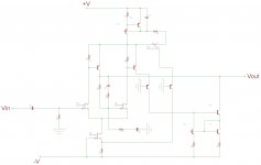
I had an idea one day. I was sitting on my porch drinking beers and it just popped in there...my head that is. I sketched out the circuit and couldn't see why it would not work so I slapped it onto a bread-board and to my surprise it did work. I've never actually simulated it, ha ha.
I've since taken it to a whole new higher level, but this is the basic idea I had for my CMCL bias. I was surprised there was no interest in it on the forum two years ago when I brought it up. But oh well, whatever....
Edit> never mind the names of the transistors, I just randomly picked them from the library for reference.
Attachments
Last edited:
BTW, the primary reason to use a cascode in the VAS is not to avoid 2nd breakdown (you will need high voltage trannies anyhow), rather to neutralize the Early effect and nonlinear behavior of Cob.
Yes, and it also allows you to use lower Vce devices for the current amplifiers. This opens up a whole new world of faster components with higher, more linear Hfe.
CBS240,
Your schematic is unclear for me I will need some time to analyze it. You use fets, is it necessary or facultative? I feel bad karma about them As you read earlier, I became spiritual, it was the only way for me to not throw my gear out of the window .... just kidding.
see ya
Your schematic is unclear for me I will need some time to analyze it. You use fets, is it necessary or facultative? I feel bad karma about them
As you read earlier, I became spiritual, it was the only way for me to not throw my gear out of the window .... just kidding.see ya
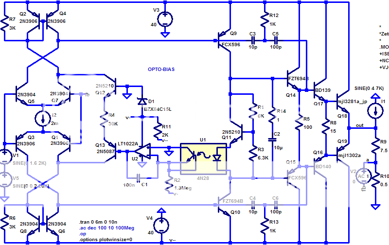
Well, J-fets are really awesome devices, IMO. I can't see how anyone doing electronic design could not see the benefits. The P-ch one is required, the others are optional. Since it is a voltage controlled device it doesn't affect the current from the CCS. The J-fet CCS is just simpler because being a depletion device it will self bias so you have just the one transistor and resistor.
R4 sets the common mode current for both legs of the VAS. If the total current of the VAS turns on more than this set point, the voltage on the collector of T3 drops. This turns on more the P-ch fet which sends more current through R1, reducing the CM current to the sources of the input transistors. The VAS transistors turn off more to strike the balance, forming the CMCL. I used the source current from the P-ch to drive the ring of two BJT CCS at the top as a short-cut and to save parts. The differential VAS is simply loaded by a Wilson mirror.
Your schematic is unclear for me I will need some time to analyze it.
R4 sets the common mode current for both legs of the VAS. If the total current of the VAS turns on more than this set point, the voltage on the collector of T3 drops. This turns on more the P-ch fet which sends more current through R1, reducing the CM current to the sources of the input transistors. The VAS transistors turn off more to strike the balance, forming the CMCL. I used the source current from the P-ch to drive the ring of two BJT CCS at the top as a short-cut and to save parts.
The differential VAS is simply loaded by a Wilson mirror.Looks like in this version of the diagram you posted Olivier73 thast the designer dropped the LTP mirror loads, presumably because of the CML problem. Having said that, Q10 and especially R18 serve no purpose. I would have returned R18 ro the emitter of th e bottom transistor in the cascode (and same for the other half of the circuit). This does improve distortion by about 20% or so - but, you need to be down at under 10ppm to see this.
A start
Edmond, and all the others too...
I attach a schematic with node voltages, currents, transient analyses, ac analyses, thd, dc temperature behavior of Iq VAS and some sensitivity figures.
The schematic is again the basic Slone topology, yes, the one with undefined VAS Iq including all features like : current mirrors, cascode, darlington, mirror image ...
To state clearly it is a IS + VAS only (no OPS attached).
The only difference with Slone is that the TPC is scrapped and replaced by a TMC principle. This to avoid getting Edmond angry
Because I have no printed version of the sensitivity analyses I can write some figures here :
The VAS Iq change rate compared to an
R1 change rate = +149 %/% !!!
R2 change rate = -112 %/% !!!
HFE Q1 change rate = -2.4 %/%
HFE Q2 change rate = +0.48 %/%
The other analyses are supplied in pdf.
The THD @ 1KHz full output swing and 10Kohms loaded VAS = 85u%
(to me thats 0.85ppm right?)
Now we all know this circuit is nice but can't work without having all the luck on your side. It's like plug and pray !
What I would like is to take this schematic as a base and then progressively introduce CMCL and other circuitry until reaching a practical design going to the pcb process...
What we want is to get the circuit workable without loosing on the THD too much !
Edmond, could you take a look if this start is good? What should we include next?
You will notice I used colours in the schematic to try to make it more readable. I also used Edmonds circuit as base so I left space in the schematic to incorporate circuitry like the CMCL etc.
I hope this is a fruitful start !
Bye for now
Attachments
-
CMCL_01_AC-analyses.pdf48.2 KB · Views: 96
-
CMCL_01_Iq VAS 0 to 50°C variation.pdf9.2 KB · Views: 78
-
CMCL_01_Schematic_Currents.pdf20.6 KB · Views: 117
-
CMCL_01_Transient_114.6Vpp.pdf134.2 KB · Views: 74
-
CMCL_01_THD 1Khz 114Vpp 86u%.pdf14.2 KB · Views: 81
-
CMCL_01_Schematic_Voltages.pdf18.6 KB · Views: 104
my sim of a optoisolator VAS current sense mirror bias cmcl:
http://www.diyaudio.com/forums/solid-state/56860-optoisolator-vas-bias-comp-diff.html#post637347
no warranty of usability... its just a sim
http://www.diyaudio.com/forums/solid-state/56860-optoisolator-vas-bias-comp-diff.html#post637347
no warranty of usability... its just a sim
Olivier73
Interesting project, Any progres so fare,
wonder to know if You are try to built the AMP
for real experimentally just to se if in real works
and maybe just try to pass some music throu it to
get some insight about its character of sound..?
I'm just curious vill fulfill Yours expectations?
I have some fets in my junk box and If Youll be
satisfied with initial progress I'll make it a Try also.
Cheers,
Alex
Hi Smiley09,
It is certainly ment to be constructed. But I want to go through all the processes.
I allready experienced a lot, however lets call it 'learning the hard way' because until now it never succeeded in building something up to final. This sounds worse than it is (I hope) because in my process and progress of building and blowing up devices I learned very much, and of-course also I thank all the DIY guys for helping me with information !
I am looking for other people to build the same project ... it would be nice to follow the same steps. We could share schematic, simulation findings, pcb design, component choices, topology choices, protection choises etc...
If you are into it, it might be helpful to read the whole thread ... you will then see why I blew so many components and also see the story of how to deal with the problem ... many posted different solutions ... some easy , some with a lot of giving in, some very complicated, some very clever, ... but mostly a combination of everything
I would say read and join our discussion ... for now I wait till Edmond Stuart returns from holiday !
bye for now
Olivier
Dear Olivier73,
Thnx for the response, I'll go to read a whole thread as You suggest,
but I vote for this amp as I found some real excellent critics about Randy's
amplifiers. If I've of more time I'd also try to participate in the early stage,
but latter I can draw a nice PCB for the Amp if You'll found it manageable.
Cheers,
Alex
next
Hi all,
Hereby the progress so far :
1. implemented CMCL
2. implemented the Vbias circuit
3. Adapted the feedback capacitor to a large value
4. I placed series resistors in the Miller Comp circuitry
5. implemented the VAS Iq maximum currrent guard
Findings :
a) the closed loop AC analyses shows a better margin than the previous one. This could partially be induced by the fact I changed some minor values here and there to optimize some results. It was done trial and error like. On the other hand I inserted series resistors in the miller circuitry. I read that a simple CAP causes a POLE which in turn causes the phase response to lage 90° ... inserting a resistor also creates a ZERO which should give a 90° phase advance... if done nicely the could somehow negate eachother making the phaseresponse look better. I am curious to hear Edmonds reply Will it be shot down or is it a good input?
b) the VAS Iq is no not dependant from R1 and R2 variations as before.
remember the ratio was about 150 %/% where now it is only almost 1 %/% !!!!
c) the temperature sweep of 50° caused IQ VAS to swing 30mA, well now it is reduced to less than 5mA !!
d) The distortion even lowered from 85u% to 8u% 110Vpp 1kHz!!!!!!!! However this must be due to the extended feedback CAP up to nearly 5mF ! Perhaps the thd of the previous circuit was also the same if the cap would have been set yet. As stated before there are also a sum of minor changes that iimpacted as well.
Could someone clear out why the feedback cap causes this change?? I suuppose because the OLG at 1KHZ is very depending on the LF freq response which is influenced by that cap ... ?
I posted other threads for OPS but no-one seems to care to answer !
Bye bye for now
Olivier
Hi all,
Hereby the progress so far :
1. implemented CMCL
2. implemented the Vbias circuit
3. Adapted the feedback capacitor to a large value
4. I placed series resistors in the Miller Comp circuitry
5. implemented the VAS Iq maximum currrent guard
Findings :
a) the closed loop AC analyses shows a better margin than the previous one. This could partially be induced by the fact I changed some minor values here and there to optimize some results. It was done trial and error like. On the other hand I inserted series resistors in the miller circuitry. I read that a simple CAP causes a POLE which in turn causes the phase response to lage 90° ... inserting a resistor also creates a ZERO which should give a 90° phase advance... if done nicely the could somehow negate eachother making the phaseresponse look better. I am curious to hear Edmonds reply
Will it be shot down or is it a good input?b) the VAS Iq is no not dependant from R1 and R2 variations as before.
remember the ratio was about 150 %/% where now it is only almost 1 %/% !!!!
c) the temperature sweep of 50° caused IQ VAS to swing 30mA, well now it is reduced to less than 5mA !!
d) The distortion even lowered from 85u% to 8u% 110Vpp 1kHz!!!!!!!! However this must be due to the extended feedback CAP up to nearly 5mF ! Perhaps the thd of the previous circuit was also the same if the cap would have been set yet. As stated before there are also a sum of minor changes that iimpacted as well.
Could someone clear out why the feedback cap causes this change?? I suuppose because the OLG at 1KHZ is very depending on the LF freq response which is influenced by that cap ... ?
I posted other threads for OPS but no-one seems to care to answer !
Bye bye for now
Olivier
Attachments
.............
I would say read and join our discussion ... for now I wait till Edmond Stuart returns from holiday !
bye for now
Olivier
Hi Olivier,
I'm back from holiday and will have a close look at your schematics. But before starting my remarks, I like to know some details:
- What kind of OPS: BJT, lateral or vertical MOSFETs; how many driver stages (1 or 2).
- Maximum output power.
- Nominal and minimal speaker impedance.
- Separate and/or regulated and/or elevated PSU for the front-end.
Gegroet, Edmond.
PS: > Perhaps the thd of the previous circuit was also the same if the cap would have been set yet.
Most likely. Allow the caps to settle. That will take a few cycles and take the distortion from the last cycle.
- Status
- This old topic is closed. If you want to reopen this topic, contact a moderator using the "Report Post" button.
- Home
- Amplifiers
- Solid State
- HEEEELLLPPP : M. Randy Slone Mirror Image Topology Construction - Troubles