Hi:
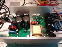
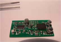
I have just finished to test my 4kw smps design, it is a commercial one made on purpose so I want to share some photos because this can be ilustrative for some forum users. It is a half bridge design using a pair of 60A Igbts working on quasi-resonant mode with the help of a series inductor and poliester capacitor.
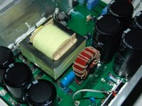
The transformer is an EE65 3F3 core wound using Litz wire and interleaved windings to keep leakage inductance as low as possible (actually 1uH or so)
I use an small housekeeping non-isolated supply on primary to control the input relay and the protection and startup timing circuits. The Igbts are controlled by an IRS2110 and a pair of 9A peak totem pole drivers and it has provision for a pair of Igbts more if needed.
The duty cycle is fixed at around 120khz with some dead time added on the oscillator side.
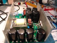
The black residue on the Igbt pins is resin not smoke, I have tested it with different Ixys and Fairchild devices to find a compromise between cost and performance.
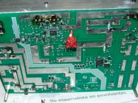
I am using a Coilcraft 30amps current sense coil for over current protection(the red one on the photo) it is in series with primary trafo to get fast response in case of short or any other anomaly to get cycle by cycle shutdown.On final board it will be on the top side of the board close to the control piggy board.
Now the input side has also provision for a PFC circuit, this one will be on a separate pcb as it was requested by customer to have 2 different versions of the supply. The final application is to feed class D modules, I will publish some photos of them as soon as they are fully tested.
All the oscillation circuitry and PWM control for fan is inside an small piggy board mounted vertically, this one will be epoxy filled by request to avoid easy copy. This is an one person job and I would like to preserve my efforts a bit more.
Regards.
I have just finished to test my 4kw smps design, it is a commercial one made on purpose so I want to share some photos because this can be ilustrative for some forum users. It is a half bridge design using a pair of 60A Igbts working on quasi-resonant mode with the help of a series inductor and poliester capacitor.
The transformer is an EE65 3F3 core wound using Litz wire and interleaved windings to keep leakage inductance as low as possible (actually 1uH or so)
I use an small housekeeping non-isolated supply on primary to control the input relay and the protection and startup timing circuits. The Igbts are controlled by an IRS2110 and a pair of 9A peak totem pole drivers and it has provision for a pair of Igbts more if needed.
The duty cycle is fixed at around 120khz with some dead time added on the oscillator side.
The black residue on the Igbt pins is resin not smoke, I have tested it with different Ixys and Fairchild devices to find a compromise between cost and performance.
I am using a Coilcraft 30amps current sense coil for over current protection(the red one on the photo) it is in series with primary trafo to get fast response in case of short or any other anomaly to get cycle by cycle shutdown.On final board it will be on the top side of the board close to the control piggy board.
Now the input side has also provision for a PFC circuit, this one will be on a separate pcb as it was requested by customer to have 2 different versions of the supply. The final application is to feed class D modules, I will publish some photos of them as soon as they are fully tested.
All the oscillation circuitry and PWM control for fan is inside an small piggy board mounted vertically, this one will be epoxy filled by request to avoid easy copy. This is an one person job and I would like to preserve my efforts a bit more.
Regards.
Attachments

Hi:
Because to get complete resonance at any loading you must dynamically change your switching frequency using any kind of feedback, I want to avoid frequency changes or PWM control because this supply is for audio purposes so quasi-resonant means to select a fixed frequency with fixed duty cycle tuned to a closer frequency respect to resonant tank, that way you get a compromise on efficiency and regulation, the current keeps sinuoidal but the output voltage is not feedback regulated, anyway I dont care too much as I will have a PFC regulating voltage on primary side and my amps have no issues with some volts tolerance on supply on the intended application .
Because to get complete resonance at any loading you must dynamically change your switching frequency using any kind of feedback, I want to avoid frequency changes or PWM control because this supply is for audio purposes so quasi-resonant means to select a fixed frequency with fixed duty cycle tuned to a closer frequency respect to resonant tank, that way you get a compromise on efficiency and regulation, the current keeps sinuoidal but the output voltage is not feedback regulated, anyway I dont care too much as I will have a PFC regulating voltage on primary side and my amps have no issues with some volts tolerance on supply on the intended application .

Not on a regular way, for feeding pro audio amps you dont need strict regulation, if not imagine the class H and AB monsters with heavy linear toroids on supply, they sag a lot during peaks, even big names like QSC or Crest Audio use non regulated smps on analog and class D amplifiers. The actual duty cycle is almost 50% so if you use a Pfc on primary side you have good and stable regulation for the main power stage and any variation on mains will be compensated on the PFC stage.Another advantage is that you can easily sync the supply with your class D amps if they use fixed frec. modulation.(Not mine)
Hi:
Because to get complete resonance at any loading you must dynamically change your switching frequency using any kind of feedback, I want to avoid frequency changes or PWM control because this supply is for audio purposes so quasi-resonant means to select a fixed frequency with fixed duty cycle tuned to a closer frequency respect to resonant tank, that way you get a compromise on efficiency and regulation, the current keeps sinuoidal but the output voltage is not feedback regulated, anyway I dont care too much as I will have a PFC regulating voltage on primary side and my amps have no issues with some volts tolerance on supply on the intended application .
Cool.
any chance of seeing a schematic without component values?
Best Regards,
Savu Silviu
Hi Savu:
No chance, I do this for living, I can answer questions but I cant expose my work completely, sorry. Anyway, the schematic alone does not mean too much, the hardest part for me was the right layout and some component selection based on my testing and past experience.
No chance, I do this for living, I can answer questions but I cant expose my work completely, sorry. Anyway, the schematic alone does not mean too much, the hardest part for me was the right layout and some component selection based on my testing and past experience.
81bas:
Around 10 volts per rail (rails are +/-120v) on heavy loading without PFC, 5 or 6 with PFC included. I design my amps to be limited around 90% of full power before 1% THD treshold so I have some voltage margin, this is to avoid heavy clipping due to duty cycle excursion, this limiting is done reading output current and voltage together on load and controlling analog input stage gain dynamically to avoid overload on active circuitry. That way the limiter can control also power output at very low loading before to put the amp in shutdown mode(this only happens on short circuit), my main target is to avoid distortion at any condition even if I have to limit the maximum power delivered by the amplifier.
Around 10 volts per rail (rails are +/-120v) on heavy loading without PFC, 5 or 6 with PFC included. I design my amps to be limited around 90% of full power before 1% THD treshold so I have some voltage margin, this is to avoid heavy clipping due to duty cycle excursion, this limiting is done reading output current and voltage together on load and controlling analog input stage gain dynamically to avoid overload on active circuitry. That way the limiter can control also power output at very low loading before to put the amp in shutdown mode(this only happens on short circuit), my main target is to avoid distortion at any condition even if I have to limit the maximum power delivered by the amplifier.
For Savu:
No, I drive the trafo with an square waveform due to the Igbt switching like others do, but on this scheme the current that flows on primary is sinuoidal due to the L+C combination added to the leakage inductance of the transformer, that way you can use Mosfets or Igbts at higher switching rates than expected with less losses, if you try to get this power with a plain half bridge the devices will heat and blow for sure as they cannot stand switching at that rate and current. Regarding your question on difference against other available supplies, the power stage has no special remarks except component selection, the only real new stuff is inside the piggy board using a Mcu for startup, control and protection tasks.
No, I drive the trafo with an square waveform due to the Igbt switching like others do, but on this scheme the current that flows on primary is sinuoidal due to the L+C combination added to the leakage inductance of the transformer, that way you can use Mosfets or Igbts at higher switching rates than expected with less losses, if you try to get this power with a plain half bridge the devices will heat and blow for sure as they cannot stand switching at that rate and current. Regarding your question on difference against other available supplies, the power stage has no special remarks except component selection, the only real new stuff is inside the piggy board using a Mcu for startup, control and protection tasks.
Around 10 volts per rail (rails are +/-120v) on heavy loading without PFC, 5 or 6 with PFC included.
It is really amazing! Thanks for the info!
")
For Savu:
No, I drive the trafo with an square waveform due to the Igbt switching like others do, but on this scheme the current that flows on primary is sinuoidal due to the L+C combination added to the leakage inductance of the transformer, that way you can use Mosfets or Igbts at higher switching rates than expected with less losses, if you try to get this power with a plain half bridge the devices will heat and blow for sure as they cannot stand switching at that rate and current. Regarding your question on difference against other available supplies, the power stage has no special remarks except component selection, the only real new stuff is inside the piggy board using a Mcu for startup, control and protection tasks.
...I allways knew that MCU's will come trough in almos every application.
It is cheaper, safer and useful to use mcu's for monitoring tasks.
you can make you're smps with mcu that saves logs onto an SD card regarding temps, voltages, courents, etc like a dataloging tool. If it blows you just download the file and see if the user was using the device right or not. Like the black box on a plane
Thanks for the reply
Does you're quasi-resonant stage look like this?
Regards,
Attachments
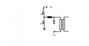
I have read about series resonant tanks in SMPS previously already somewhere. It looks like a "self-regulating" circuit for me But I was not able to believe, that it is so simple to build such a high power SMPS using this topology. As I understand, with low load or with no load the inductance of transformer's primary is high and overall Fres is much lower, than actual switching frequency of the half bridge. So resonance does not occur, and the current in primary is low. With applying the load, inductance of transformer's primary quickly drops to some few uH (leakage inductance), overall Fres increases and almost matches the switching frequency of the half bridge (it should be done by design). Resonance occurs and provides high current to the output... Somehow like this...
But I was not able to believe, that it is so simple to build such a high power SMPS using this topology. As I understand, with low load or with no load the inductance of transformer's primary is high and overall Fres is much lower, than actual switching frequency of the half bridge. So resonance does not occur, and the current in primary is low. With applying the load, inductance of transformer's primary quickly drops to some few uH (leakage inductance), overall Fres increases and almost matches the switching frequency of the half bridge (it should be done by design). Resonance occurs and provides high current to the output... Somehow like this... Well explained. The supply is on hard swiching mode during idle times(you can confirm this as the Igbts get warm and looking at scope on the secondary winding of the current sense coil) but the current is very low so the devices dont suffer, as soon as the load increases the supply approach resonance and current becomes more sinuoidal shaped so some self regulation is obtained as you are approaching resonance point as the current grows,the duty cycle is always near 50% you cant get uncontrolled voltage increase on output due to pulse modulation and when the current is moderate the Igbts are a bit colder than at idle due to the sinuoidal current that is forcing soft switching through them.
- Status
- This old topic is closed. If you want to reopen this topic, contact a moderator using the "Report Post" button.
- Home
- Amplifiers
- Power Supplies
- My 4Kw smps finished