Hi Everyone,
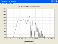
Attachment 1 shows the Hornresp power response prediction for the William Cowan 60 hertz tapped horn with Eighteen Sound 10W400 driver, radiating into 2 Pi space.
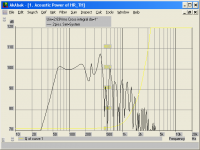
Attachment 2 shows the AkAbak power response prediction for the same system, radiating into 2 Pi space.
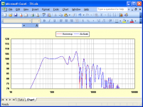
Attachment 3 compares the power response data exported from Hornresp with that exported from AkAbak. The results are not precisely the same because of slight differences in the values of the frequencies sampled by the two programs. I can’t see how the model results could be interpreted as being "quite different", though") .
.
Kind regards,
David
Ron K wrote: according to Tom Danley, Akabak models quite differently then Horn Response.
Attachment 1 shows the Hornresp power response prediction for the William Cowan 60 hertz tapped horn with Eighteen Sound 10W400 driver, radiating into 2 Pi space.
Attachment 2 shows the AkAbak power response prediction for the same system, radiating into 2 Pi space.
Attachment 3 compares the power response data exported from Hornresp with that exported from AkAbak. The results are not precisely the same because of slight differences in the values of the frequencies sampled by the two programs. I can’t see how the model results could be interpreted as being "quite different", though
.Kind regards,
David
Attachments
Hornresp have multiple times been shown to resemble the real world very accurately.
As long as you know what you model and actually build it.
Both in directivity response, output and excursion.
The biggest gray area is when you start folding a pipe or TH where you simply don't know what you simulate, or how it behave in real world.
Q of resonances differs a lot here, but in a good way.
Time to take the new version out for a test drive now.
Hi Everyone,
Just to explain a bit further.
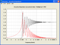
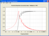
The following example illustrates the difference between the throat acoustical impedance results produced using a plane wavefront model, and those produced using an isophase wavefront model, for a large-mouth 100 hertz exponential horn.
Attachment 1 shows the plane wavefront model results, identical to those produced by AkAbak, compared to the results for an equivalent infinite horn.
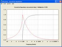
Attachment 2 shows the isophase wavefront model results, as produced by Hornresp, compared to the results for an equivalent infinite horn.
Attachment 3 shows the results for the infinite 100 hertz exponential horn, separately.
For a constant flare, as the horn becomes longer and the mouth becomes larger, the throat acoustical impedance results should tend asymptotically towards the infinite case. This happens with the Hornresp isophase model but not with the AkAbak plane wavefront model.
Kind regards,
David
AkAbak uses a plane wavefront model in all cases, meaning that results can become less accurate once Cir exceeds 1.
Just to explain a bit further.
The following example illustrates the difference between the throat acoustical impedance results produced using a plane wavefront model, and those produced using an isophase wavefront model, for a large-mouth 100 hertz exponential horn.
Attachment 1 shows the plane wavefront model results, identical to those produced by AkAbak, compared to the results for an equivalent infinite horn.
Attachment 2 shows the isophase wavefront model results, as produced by Hornresp, compared to the results for an equivalent infinite horn.
Attachment 3 shows the results for the infinite 100 hertz exponential horn, separately.
For a constant flare, as the horn becomes longer and the mouth becomes larger, the throat acoustical impedance results should tend asymptotically towards the infinite case. This happens with the Hornresp isophase model but not with the AkAbak plane wavefront model.
Kind regards,
David
Attachments
Hi Everyone,
Speaking of source code, some users might find the following of interest.
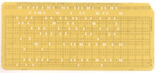
The attachment shows one of the 80-column Hollerith input punch cards taken from the original Hornresp source code listing. I still have the complete set of cards for the program - they are now more than 40 years old. The deck of cards making up the program is 8 cm thick.
The actual Fortran IV code statement can be seen printed at the top of the card. It represents one line from the subroutine responsible for calculating the throat acoustical impedance of a finite conical horn.
The original Hornresp program ran as a batch file on a room-size mainframe computer.
Kind regards,
David
David do you make your source code available?
Speaking of source code, some users might find the following of interest.
The attachment shows one of the 80-column Hollerith input punch cards taken from the original Hornresp source code listing. I still have the complete set of cards for the program - they are now more than 40 years old. The deck of cards making up the program is 8 cm thick.
The actual Fortran IV code statement can be seen printed at the top of the card. It represents one line from the subroutine responsible for calculating the throat acoustical impedance of a finite conical horn.
The original Hornresp program ran as a batch file on a room-size mainframe computer
.Kind regards,
David
Attachments
I don't have the data for the horns David posted, but here's a comparison of the throat impedance of a large exponential horn in an infinite baffle (CIR=2), simulated both in Hornresp and in BEM. Again, Hornresp is quite close, and David is right about the fact that the throat impedance gets smoother as the mouth size is increased beyond CIR=1.
Bjørn
Bjørn
Attachments
Using loudspeaker wizard on this data gives me "Run-time error 6: Overflow"
ID=26.40
Ang=2.0 x Pi
Eg=2.83
Rg=0.00
Fta=0.00
S1=100.00
S2=100.00
Con=20.00
F12=0.00
S2=0.00
S3=0.00
L23=0.00
F23=0.00
S3=0.00
S4=0.00
L34=0.00
F34=0.00
S4=0.00
S5=0.00
L45=0.00
F45=0.00
Sd=490.00
Bl=8.50
Cms=1.10E-03
Rms=1.00
Mmd=63.10
Le=1.60
Re=3.60
Nd=1
Vrc=20.00
Lrc=20.00
Ap1=0.00
Lpt=0.00
Vtc=8000.00
Atc=1000.00
Com=MGR 12" BP
The attachment shows one of the 80-column Hollerith input punch cards taken from the original Hornresp source code listing. I still have the complete set of cards for the program - they are now more than 40 years old. The deck of cards making up the program is 8 cm thick.
Boy does that bring back memories!
I just missed punch cards and Fortran. I'm not that old! But I remember having to take all the fundamentals in Computer Science. Thanks for the trip down memory road David.
So if I have this figured out correctly you have been doing horn simulations for what 35 years? Maybe 40?
Explains the thoroughness of the program. And I have yet to see anyone do as tight code as you. All the functionality in still less than a MB. Nice.
THe computers I took programing on were memory enhanced to 32 Kb and ran on Z80 processors. My high level language was the precursor to C. Turbo Pascal. Those were the days when I had hair! LOL
I have but one comment to make on Hornresp's accuracy. The little wierd bandpass variant I worked out checked in as almost perfect to the hz and magnitude of the drivers impedance in box. I have to say I was floored. I think I posted a comment back then and I have unfortunately lost the screen shots but considering that the box was neither a horn or a normal vented or sealed box your method of calulating the resulting output and the impedance magnitude is most impressive.
Mark
Mark
If ya still need some blank ones, I have more than 8cm of those. They make pretty good bookmarkers.Hi Everyone,
Speaking of source code, some users might find the following of interest.
The attachment shows one of the 80-column Hollerith input punch cards taken from the original Hornresp source code listing. I still have the complete set of cards for the program - they are now more than 40 years old. The deck of cards making up the program is 8 cm thick.
The actual Fortran IV code statement can be seen printed at the top of the card. It represents one line from the subroutine responsible for calculating the throat acoustical impedance of a finite conical horn.
The original Hornresp program ran as a batch file on a room-size mainframe computer
Kind regards,
David
I don't have the data for the horns David posted, but here's a comparison of the throat impedance of a large exponential horn in an infinite baffle (CIR=2), simulated both in Hornresp and in BEM.
Hi Bjørn,
Many thanks for this. I used a somewhat more extreme example than you did, just so that the trend towards the infinite case could be clearly seen. The relevant Hornresp parameter values are Ang = 2,0 x Pi, S1 = 10,00, S2 = 75335,04 and L12 (Exp) = 244,38, giving F12 = 100,00 hertz, Cir = 4,00 and AT = 1,87 degrees.
While a Cir value of 4 is unlikely to be used in practice, the example serves to illustrate the considerable difference between plane and isophase wavefront models when applied to horns with large mouth Fta values. It is certainly necessary to use an isophase model for Le Cléac'h, spherical wave and tractrix horns, to obtain reasonably accurate results.
It is interesting that with the BEM simulation results, the resistive component of the normalised throat impedance appears to tend towards a value just above 0,9 rather than to 1, at the higher frequencies.
Kind regards,
David
Using loudspeaker wizard on this data gives me "Run-time error 6: Overflow"
Hi David_Web,
Many thanks for this!
I get the same error - I will let you know when the bug is fixed.
Kind regards,
David
Hi Mark,
I started in 1970. Through the results of my early simulations I actually became aware of the plane wavefront model Cir > 1 limitation some time before Don Keele published his findings in the 1973 "Optimum Horn Mouth Size" AES paper. Don mistakenly concluded that the limitation was due to the characteristics of the horn itself, rather than to the model he was using to simulate it. I had already concluded otherwise .
Thanks. The code could be a lot tighter still, but then it would be more difficult for me to understand and maintain.
Thanks again.
Kind regards,
David
So if I have this figured out correctly you have been doing horn simulations for what 35 years? Maybe 40?
I started in 1970
. Through the results of my early simulations I actually became aware of the plane wavefront model Cir > 1 limitation some time before Don Keele published his findings in the 1973 "Optimum Horn Mouth Size" AES paper. Don mistakenly concluded that the limitation was due to the characteristics of the horn itself, rather than to the model he was using to simulate it. I had already concluded otherwise .Explains the thoroughness of the program. And I have yet to see anyone do as tight code as you. All the functionality in still less than a MB. Nice.
Thanks. The code could be a lot tighter still, but then it would be more difficult for me to understand and maintain
.I think I posted a comment back then and I have unfortunately lost the screen shots but considering that the box was neither a horn or a normal vented or sealed box your method of calculating the resulting output and the impedance magnitude is most impressive.
Thanks again
.Kind regards,
David
40 years is a great part of the time I have been alive!
I have read papers by a great deal of gentlemen that have been called audio giants or pinacle figures. I have never had the priviledge of speaking to them or any form of ciommunication.
It is indeed a rare thing to be able to communicate with the giant whose shoulders we stand on. We all start from a point of knowing little to nothing. Then we add on this with experience. Those who have a great deal of experience like David are indeed showing us the way to get things accomplished not by shear trial and error but with wisdom and clear reasoning. So being able to ask questions and get answers from someone who has been at this for so long a time is indeed a great priviledge. To be able to say that he figured out something before Don Keele for instance is wonderfull. I have no doubt what so ever in the work Mr. McBean has furnished us. I thank you for being able to broaden my own understanding of horn design and function. And I am at this point as a designer because of being pointed in the right direction by Mr. McBean.
You have my profound thanks!
Mark
Bug Fixed
Hi David_Web,
The bug has now been fixed - the latest Hornresp release is Product Number 2640-100508. Thanks again for bringing the problem to my attention.
Kind regards,
David
I get the same error - I will let you know when the bug is fixed.
Hi David_Web,
The bug has now been fixed - the latest Hornresp release is Product Number 2640-100508. Thanks again for bringing the problem to my attention.
Kind regards,
David
Thanks. It works great.
The driver still sucked for normal sized BP regardless how easy hornresp was to use. The changed sliders really worked great when volume increased.
Can the "scroll speed" when scrolling by clicking on the side of the slider (instead of the arrow) be increased at the same time?
The driver still sucked for normal sized BP regardless how easy hornresp was to use. The changed sliders really worked great when volume increased.
Can the "scroll speed" when scrolling by clicking on the side of the slider (instead of the arrow) be increased at the same time?
- Home
- Loudspeakers
- Subwoofers
- Hornresp