I'm trying to simulate a speaker with a jx92s driver using Hornresp and MJK's worksheets.
Before I can really make anything out from the sims I need to know what I'm looking at.
I'll start with uploading 4 images, two from each program.
How would you expect this speaker to sound?
I'm not saying this is the final draft or anything like it.
It's a first stage experiment while learning the software.
The graphs look very uneven and scary, but how would one expect it to sound?
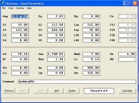
#1 = Hornresp terminus
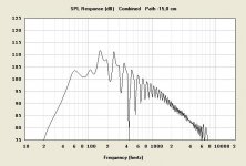
#2 = Hornresp combined
#3 = MJK SPL plot
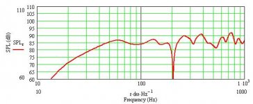
#4 = MKJ Combied SPL + diffraction (baffel step)
Before I can really make anything out from the sims I need to know what I'm looking at.
I'll start with uploading 4 images, two from each program.
How would you expect this speaker to sound?
I'm not saying this is the final draft or anything like it.
It's a first stage experiment while learning the software.
The graphs look very uneven and scary, but how would one expect it to sound?
#1 = Hornresp terminus
#2 = Hornresp combined
#3 = MJK SPL plot
#4 = MKJ Combied SPL + diffraction (baffel step)
Attachments
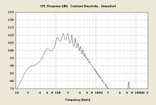
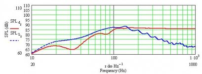
they sure don't agree - I'll assume Hornresp can't model the effects of damping material (?) "If" it acted like the Hornresp model then the "hit" region would be emphasized - perhaps too much (maybe not?) and would have pretty good bass punch. Your MJK predictions look pretty smooth. There should be enough real measurements of MJK modeled projects to give a feel. I made a 15" transflex type and Hornresp was pretty accurate for that case--but it had no stuffing along the line.
Hmm, well to me, once you get the scales the same, they seem to be at least largely similar, but freddi, you know much more than I do.
1. Which MJK worksheet is that from? TL Sections or one of the BLH sheets?
2. MJK models room factors, not just walls / corners but also floor bounce, etc.
3. I can't see how HornResp would deal with baffle step as MJK is doing there, since it deals with areas/lengths (not widths as far as I can tell).
I am a newb so don't put any stock in what I've said. Like you, I'm highly interested and curious!
Hi markusG, oops, more thoughts:
4. What is HornResp using for Ang -- .5 (corner)?
5. Path length?
6. Is this a BVR or BLH? As I'm sure you know, BVR = big chamber like a BR, short path (maybe 10 liters chamber / <1m length) whereas BLH would be more like small chamber / long path (maybe 2 liters chamber / > 1.4m length).
7. You ask "how would this speaker sound" and I believe you can get another 10Hz, maybe 20Hz on the bottom.
Hi freddi,
Well I guess it's the differences that are most interesting") You've measured lots and lots, whereas I'm just coming up to speed (if that).
You've measured lots and lots, whereas I'm just coming up to speed (if that).
markusG, in my extremely limited experience, when you model the horn by itself, you can achieve a "plateau" where there are no ripples. And then on the right side of that plateau, you get your first "bump" and then you get more ripple as the high frequency response drops.
The sides of the plateau are obviously related to the length. For example, if your length is about .7 meters (assuming a BVR), the right side of the plateau may be at ~120Hz (half wavelength) and the left side may be at ~60Hz (quarter wavelength).
Well I guess it's the differences that are most interesting
You've measured lots and lots, whereas I'm just coming up to speed (if that).markusG, in my extremely limited experience, when you model the horn by itself, you can achieve a "plateau" where there are no ripples. And then on the right side of that plateau, you get your first "bump" and then you get more ripple as the high frequency response drops.
The sides of the plateau are obviously related to the length. For example, if your length is about .7 meters (assuming a BVR), the right side of the plateau may be at ~120Hz (half wavelength) and the left side may be at ~60Hz (quarter wavelength).
Last edited:
Back engineer some commercial BLHs (or any one you can get the plan), and plug the numbers into hornrep, you'll find out many of them have similar (ragged) responses as markusG had on the above.
Too small of the mouth (terminus) area, improper proportion of the cross section areas, wrong expansions, unmatched back chambers.... etc. are all very easily getting ragged responses. Certain efforts (or experiences) are needed to get that nice looking 'plateau', even in the sims. When making a real thing, epecially a commercial product, all kinds of compromises cut things here and there....
Hi markusG, can we see the input screen (of hornresp)?
freddi> I think you are correct about hornresp, it's more limited. Chambersize, diffraction and stuffing isn't factored in afaik?
rjbond3rd> I'm using the BLH sheet with sections. The lengh of the horn is a little over 100".
CLS> Picture of the input screen comming right up...
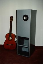
My objectiv is to come up with a FR BLH that doesn't need bsc. I'm modelling a VERY narrow cabinet with a height of roughly 3'-4'. I'm aiming for 4' with the driver offset a little heightwise, maybe 3'2" off the ground or something along those lines?
Looking at "edge" (the software) you get a smooth baffel step but MJK uses a sinusoidal **. The peaks and dips in the graphs, are they to be ignored or will they make the speakers sound odd? Do I assume a rough mean value to be the right one or will the SPL fluctuate lke it does in the graphs? How does that sound?
rjbond3rd> I'm using the BLH sheet with sections. The lengh of the horn is a little over 100".
CLS> Picture of the input screen comming right up...
My objectiv is to come up with a FR BLH that doesn't need bsc. I'm modelling a VERY narrow cabinet with a height of roughly 3'-4'. I'm aiming for 4' with the driver offset a little heightwise, maybe 3'2" off the ground or something along those lines?
Looking at "edge" (the software) you get a smooth baffel step but MJK uses a sinusoidal **. The peaks and dips in the graphs, are they to be ignored or will they make the speakers sound odd? Do I assume a rough mean value to be the right one or will the SPL fluctuate lke it does in the graphs? How does that sound?
if your length is about .7 meters (assuming a BVR), the right side of the plateau may be at ~120Hz (half wavelength) and the left side may be at ~60Hz (quarter wavelength).
1. Oops, that's not right! 120hz full wavelength is ~2.86m. The The quarter wavelength is .75m. Sorry about that.
2. Attached is a completely un-refined (!) JX92S BVR for your possible amusement.
3. Mr. Horst, regarding AJ Horn, how does one input the flare frequency? Is it necessary to calculate the horn parameters outside AJ Horn, then input the mouth, throat, length for simulation?
Attachments
Hello,
i don´t knew a simu-software
where k (flare rate) is used,
you need to know it by yourself,
like the real and the blind part
of a horn.
may be helpful:
Calculation of expo horns
If you have AH, AM, l,
k still lacks the flare rate:
ln (AM / AH) / l = k
so you can see the surface
each point out (Al):
INV ln (l * k) * AH = Al
l m, AH + AM + AL in square meters
By Al e.g. m in width and divide
you have the distance in meters
AH = Horn throat
AM = Horn mouth
k = flare rate
l = length
Lengths and flare rate VALUES
K VALUES:
0.37 ~ 10 Hz
0.55 ~ 15 Hz
0.7 ~ 19 Hz
0.9 ~ 25 Hz
1.1 ~ 30 Hz
1.3 ~ 35 Hz
1.48 ~ 40 Hz
About an octave above k plays the horn,
if the length matches. At BL horn lengths
over 3.4 m, you get a suck out
below 100 Hz
4/lamda lengths VALUES
3.4 m ~ 25 Hz
2.8 m ~ 30 Hz
2.4 m ~ 35 Hz
2.1 m ~ 40 Hz
1.7 m ~ 50 Hz
1.4 m ~ 60 Hz
Most of my horns open
the last~ 75 cm (look ALPHORN)
with a double or triple k,
to get a better mouth+room
crossover.
i don´t knew a simu-software
where k (flare rate) is used,
you need to know it by yourself,
like the real and the blind part
of a horn.
may be helpful:
Calculation of expo horns
If you have AH, AM, l,
k still lacks the flare rate:
ln (AM / AH) / l = k
so you can see the surface
each point out (Al):
INV ln (l * k) * AH = Al
l m, AH + AM + AL in square meters
By Al e.g. m in width and divide
you have the distance in meters
AH = Horn throat
AM = Horn mouth
k = flare rate
l = length
Lengths and flare rate VALUES
K VALUES:
0.37 ~ 10 Hz
0.55 ~ 15 Hz
0.7 ~ 19 Hz
0.9 ~ 25 Hz
1.1 ~ 30 Hz
1.3 ~ 35 Hz
1.48 ~ 40 Hz

About an octave above k plays the horn,
if the length matches. At BL horn lengths
over 3.4 m, you get a suck out
below 100 Hz
4/lamda lengths VALUES
3.4 m ~ 25 Hz
2.8 m ~ 30 Hz
2.4 m ~ 35 Hz
2.1 m ~ 40 Hz
1.7 m ~ 50 Hz
1.4 m ~ 60 Hz
Most of my horns open
the last~ 75 cm (look ALPHORN)
with a double or triple k,
to get a better mouth+room
crossover.
hm> I'm only just starting out. I didn't even calcultate the k value, I used a 10:1 ratio I think?
I also tried to understand what you wrote in your last post but it doesn't really do anything for me. I understand the calculations somewhat but it doesn't really help the simulations.
My main issue is sonic signature due to uneven SPL simulations. The computer models are only an estimate of the real world. Is this just a case of "graphs looking horrible but it'll still sound good"? Or will it result in an annoying sonic signature? You get hearing fatigue and so on? Something's off but you can't put your finger on it... That sort of fealing?
I'm hoping for the first option, i.e. it'll still sound great despite the ugly graphs.
Hello,
most LS catalog measurements looking linear
because they smoothed the graphs over 1 oktave,
i dont, i take only 1/3 oktave smoothing so my graphs
looking more realistic, if you can interpret it, not nice, not
so sellable as Ls producers need.
But i´ve done measurement, others didn´t!!
How many measurements did you do?
i think you better look on my constructions and simulate it
compair it to my measurement, as an first construction
it is better to build a known construction to learn
before construct your own.
The point is not the simu and the math, it is to
fould it in a small enclosure.
hm> I was talking about my own graphs. They are very uneven and I'm unsure how to interpret them.
I wasn't passing any judgement on your work.
I'm just trying to figure out what to make of my own simulations. When is it linear enough to try building a cabinet?
In your last sentence you hit the nail on the head. I'm trying to use a very narrow cabinet and avoiding using bsc.
My goal
- width (inner dimension) 120mm
- Height (inner dimension) 100-120cm
- Driver position (from floor) 95cm +/- 5cm
- Depth, as little as possible but not any less
- No bsc needed
- 50Hz f3 is ok, 40Hz would be great
Last edited:
like this?:

kornett
measurements with single simu
kornettmess
understandable here (scroll down):
about what
plan
Kornettplan
if you take 100mm inner width you can take
3" driver i prefer:
http://www.speaker-online.de/download/10WB0824-G00.pdf
and invers a cheap 3-4"

kornett
measurements with single simu
kornettmess
understandable here (scroll down):
about what
plan
Kornettplan

if you take 100mm inner width you can take
3" driver i prefer:
http://www.speaker-online.de/download/10WB0824-G00.pdf
and invers a cheap 3-4"
The kornett was definately different.
I'm not sure about either bipole or dipole? However, If I stick with the Jordan jx92s drivers it would be possible to buy an extra pair and run two drivers per cabinet. (I already have one pair.)
If connected in series it would raise the impedance which would be good for OTL tube amps. (I'll be building a set of M60's)
Something worth looking into anyway.
I'm a horn n0ob so designing a double horn is two steps further along than I am at this point.
The kornett probably would pass the wife's inspection. She's the one who proposed the design criterias.
- Status
- This old topic is closed. If you want to reopen this topic, contact a moderator using the "Report Post" button.
- Home
- Loudspeakers
- Full Range
- Help interpret graphs?