")
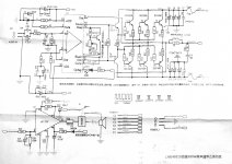
the compensation goes between pin 6 and ground ie 3.3kohm in series with 75pf between pin 6 and ground. It's in one of the lme49810 11 30 threads but I can't remember which one. Don't know how it sounds cause my basement speakers are bi-amped and the living room speakers I don't want to risk blowing them up till I am satisfied they are reliable. They are a pair of Bailey/Rodgers TL's using kef speakers from I think Hi-FI answers article in the 70's. Kef parts are like gold now. My son destroyed all of the t27's and the super tweeters I still haven't found proper replacements. I am currently using some old (30 years) Philips domes for the time being. I think I finally figured how to take some close up shots, with luck I will post em but don't hold your breath.
They are a pair of Bailey/Rodgers TL's using kef speakers from I think Hi-FI answers article in the 70's. Kef parts are like gold now. My son destroyed all of the t27's and the super tweeters
I built those as well -- got the KEF parts from another DIY'r on Long Island -- and my son blew out the T27's as well. These were replaced with Audax.
At one time you could purchase KEF parts in New York City. I recall that shipping times from the UK were something like 8-weeks.
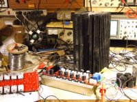
here is where I put the RC network to stop a tiny oscillation. Mark suggested 3.3k+75pf what I had on hand was 3.9K+82pf. works well. I had the boards on and off the heat sinks so many times, you can tell I got pretty sloppy with the grease. 13 screws off 13screws on
Attachments
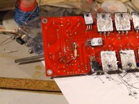
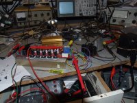
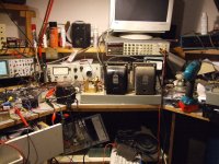
Hey I spent a few days cleaning up before I took the pictures. Fortunately the camera doesn't do 360. Yea I id a bunch of stuff to it. Power supply is outside and +/- 22vdc, power lamp is now a led, meter is buffered with an on/off switch and a 1000uf across the meter, square waves are also on off, the main board is now an lmeXXXX based oscillator, one of the +/- 22volt ones.
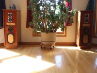
Here is a pic of my kefs I made them when the wife was pregnant, our daughter is 23 now.
Here is a pic of my kefs I made them when the wife was pregnant, our daughter is 23 now.
Attachments
Here is a pic of my kefs I made them when the wife was pregnant, our daughter is 23 now.
I thought you meant the "Pro-9TL":
An externally hosted image should be here but it was not working when we last tested it.
You find when tweaking the comp that the THD can be traded off for slew rate and stability!
junglejuice;2151916 are these amp boards any good said:which.
Post21 schematic or something else?
which.
Post21 schematic or something else?
Yes the schematic that is shown in post #21 is the one I am referring to, are they any good, do they sound any good?
are the LME498xx design any good? Look up the other threads discussing these implementations at length.
Is this particular PCB implementation any good? Buy one and find out?
Will this particular implementation drive a 2ohm or 2r0 load? Check the output stage and driver stage currents for typical operational conditions.
Is this particular PCB implementation any good? Buy one and find out?
Will this particular implementation drive a 2ohm or 2r0 load? Check the output stage and driver stage currents for typical operational conditions.
- Status
- This old topic is closed. If you want to reopen this topic, contact a moderator using the "Report Post" button.
- Home
- Amplifiers
- Solid State
- Anyone recognise this Design..? based on LME49810