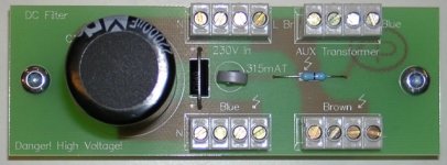
Sorry that i posted the DC filter without further analysys.
I simply copied it from the LC Audio Website.
On the other hand it may be good that i posted it because people that read this thread are now warned about the danger of this circuit.
I read the schematic as using a transorb not a zener. Yes the zener symbol was used to make things inaccurate. A transorb can be made quite large to handle large jolts of energy. Some are essentially zeners triggering power mosfets. Some are bidirectional, I assume that is what is used here.
I suspect the actual device is not quite built as the schematic shows, or else the manufacturer probably would have noticed the explosions.
So the lesson is when you steal circuits, sometimes you may pay a penalty!
Last edited:
Designing a power transformer isn't simple and a lot of aspects are involved. You need more metal for lower frequencied to keep the sme flux level. At the same time most commercial transformer vendors try to run their transformers pretty close to saturation. They get higher efficiency for both power and dollars, but the distortion in the core goes up, noise from loose lams and magnetostriction goes up, heat goes up and usually the sound degrades. Further most audio designers end up with very small conduction angles, creating lots of harmonic energy which in turn makes more noise both magnetically and radiated. The small conduction angles also require much larger transformers because the VA requirements depart a lot from the watts needed.
Add a little DC (.5V) and you can push the transformer over the edge.
On this we are in complete agreement, but the question is if regularly switching the AC line, thus the DC offset, will keep the transformer from saturating. I.E. how long does it really take the AC power line's DC offset to affect audio equipment?
Second is there a way to detect the saturation in the core and apply a correction offset. Or is the correction offset even needed if we have an equally offset load current?
Last edited:
I think the DC effects on the transformers will be essentially instantaneous. It seems its not well known that a transformer that has its primary interrupted at a peak on the sine wave will stay magnetized at almost that level. This is why you can blow fuses with a large toroid on turn on, its core is saturated from the turn off. Totally intermittent but when it happens the toroid is a dead short on the line. The AC signal will ensure the magnetization of the core (like bias on a magnetic tape).
I would look at the DC current into the transformer and apply a bucking current to a winding to fix it. An interesting design challenge, especially the bootstrap issues. I would ignore DC voltage since its the current that matters. Anyone looking to patent this should look at the instructions for the Tek high current probes, its described there.
However designing BT level stuff I would get my vendor to run the transformer at 1/2 the normal flux level. I have found that makes a bigger difference. Then its issues of primary to secondary isolation. Shields aren't enough. Finally optimizing the current profile of the load. Spread the conduction angle out as far as possible if you can.
Last edited:
Demian,
On this we disagree. This may be a case of practice versus theory.
If the distortion is uncorrelated then the total distortion is calculated by the RMS method or the square root of the sum of the averages (mean) squared. On this we seem to disagree.
In some cases the distortion adds linearly when it is phase coherent. If I take two resistors each with 1 volt of signal across them creating 1nV of distortion the total distortion is 2nV across both and of course the signal is now 2 volts so the % of distortion remains the same. It does not go down by the square root of sources as random distortion or noise would. That is because the distortion is generated by the exact same mechanism and signal.
That is why when I parallel instrumentation amplifiers for lower noise, the noise does go down but the distortion does not.
I think we are both tripping over semantics. First distortion products will be by nature correlated to their excitation signals (both THD and IM). Then if the excitation is common on several stages (the cases I think you are discussing) then the distortion products will be correlated. However the type of correlation isn't too predictable. But, since they are correlated they can't be added like random noise. Your example of the inamps is a good example. Its possible that two different inamps with similar primary characteristics could cancel (really unlikely) or add in many different but consistent ways. Enough math and you may get there but measurements and listening are much faster.
( Side topic: there are many contributors in this thread who are interested in distortion measurement / assessment. A new member has posted a fresh approach over in the Software Tools section. Perhaps of interest to you? http://www.diyaudio.com/forums/soft...re-audible-distortion-signal-degradation.html )
the manufacturer probably would have noticed the explosions.
Honestly I think the reason is likely that rarely more than 1.5V volts DC is present on mains. I found that it also varies constantly, so I guess the cap just doesn't see reversed polarity for a sufficiently long time.
If you look in the web, there are many dangerous variations on this and yet it seems not much happens. That's really fortunate. Even more so as it seems that even experienced designers are not aware of this problem and design according to their common sense (a few volts won't hurt...).
Have fun, Hannes
The cap does not care if its ratings are exceeded by DC or by AC. What it cares is that something is in parallel that shortens it out of the path before it reaches the 1.5 Volt or so.
On a separate note: Conrad carry also Beyschlag 0414 1 Watt resistors (if they are genuine Beyschlag). Possibly maybe they sound even better than the smaller ones.
On a separate note: Conrad carry also Beyschlag 0414 1 Watt resistors (if they are genuine Beyschlag). Possibly maybe they sound even better than the smaller ones.
Honestly I think the reason is likely that rarely more than 1.5V volts DC is present on mains. I found that it also varies constantly, so I guess the cap just doesn't see reversed polarity for a sufficiently long time.
If you look in the web, there are many dangerous variations on this and yet it seems not much happens. That's really fortunate. Even more so as it seems that even experienced designers are not aware of this problem and design according to their common sense (a few volts won't hurt...).
Have fun, Hannes
Hannes,
I am quite sceptic about all this DC on the mains. Did you ever measure this?
If there is DC, why doesn't it heat up all transformers in my systems, and if it does, where is all that power then coming from?
What am I missing?
jd
I think we are both tripping over semantics. First distortion products will be by nature correlated to their excitation signals (both THD and IM). Then if the excitation is common on several stages (the cases I think you are discussing) then the distortion products will be correlated. However the type of correlation isn't too predictable. But, since they are correlated they can't be added like random noise. Your example of the inamps is a good example. Its possible that two different inamps with similar primary characteristics could cancel (really unlikely) or add in many different but consistent ways. Enough math and you may get there but measurements and listening are much faster.
Demian,
If we both agree on anything the moderators will ban us. Forums appear to be only for flamers to argue!
So let us just say we both get the same answers.
The issue of two different amplifiers canceling distortion actually was used in the early days of Cable TV, but it really didn't work over real conditions of temperature etc.
The important issue as I see it is that at the design level one can approximate where similarly stressed components may add and by a different design topology they may cancel.
I think the DC effects on the transformers will be essentially instantaneous. It seems its not well known that a transformer that has its primary interrupted at a peak on the sine wave will stay magnetized at almost that level. This is why you can blow fuses with a large toroid on turn on, its core is saturated from the turn off. Totally intermittent but when it happens the toroid is a dead short on the line. The AC signal will ensure the magnetization of the core (like bias on a magnetic tape).
I would look at the DC current into the transformer and apply a bucking current to a winding to fix it. An interesting design challenge, especially the bootstrap issues. I would ignore DC voltage since its the current that matters. Anyone looking to patent this should look at the instructions for the Tek high current probes, its described there.
However designing BT level stuff I would get my vendor to run the transformer at 1/2 the normal flux level. I have found that makes a bigger difference. Then its issues of primary to secondary isolation. Shields aren't enough. Finally optimizing the current profile of the load. Spread the conduction angle out as far as possible if you can.
Yes as the magnetic material is driven through the BH loop if you stop the excitation current the material will stay at that state. The issue is: is there a secondary effect of a low level constant bias?
If so a DC compensation circuit would reduce energy loss or the creation of more harmonics.
However a correction circuit by itself would only slow the problem as even a correction circuit is not perfect. So a reversal of the mains would still be required periodically.
An interesting question arises is that if the AC mains is clipped unevenly, is that waveform passed to the secondary? This would depend on the bandwidth of the transformer.
Symmetry in current through a core is a basic principle but not actually seen in practice, as a result transformers must be designed for some DC bias. This can be done intentionally or just by following the rules of thumb commonly used for transformer design.
The current design activity is on high frequency switchers which tolerate very little DC.
As to spreading the conductivity angle this can be done by inductance or winding resistance. It was a bit surprising when I started looking at how diodes really rectify.
So back to the question, has anyone actually tried a reversing switch?
I think the DC effects on the transformers will be essentially instantaneous.
That is correct. An engineer I worked with added a separate winding to a transformer he designed to be used as a dimmer for neon lighting. Applying a small DC voltage to that winding would dim the light. This was done to make the sign blind bright then dim to attract more attention. The blinking rate could be very high if so desired.
It seems its not well known that a transformer that has its primary interrupted at a peak on the sine wave will stay magnetized at almost that level. This is why you can blow fuses with a large toroid on turn on, its core is saturated from the turn off. Totally intermittent but when it happens the toroid is a dead short on the line. The AC signal will ensure the magnetization of the core (like bias on a magnetic tape).
That is possibly better known than you think, at least among transformer designers and the people that work with them. That same engineer designed a circuit that cut power to our larger transformers only at the zero crossing. Turn was also controlled to minimize inrush current.
You meant demagnetization didn't you?
The amount of DC voltage is not as important as the ampere turns on the primary.
Did you ever measure this?
Hi Jan,
I didn't do long term (ie. full day or so) measurements, so maybe I missed the largest values, however the 10 minutes or so I did measure I found values up to 0.7 V_DC.
Certainly not large enough to cause serious problems (trafo heating), but enough to cause toroid humm.
Have fun, Hannes
That is correct. An engineer I worked with added a separate winding to a transformer he designed to be used as a dimmer for neon lighting. Applying a small DC voltage to that winding would dim the light. This was done to make the sign blind bright then dim to attract more attention. The blinking rate could be very high if so desired.
That is a delightful throw back to the 40's a current controlled variable reactor! Still used in many places but the first major user I think was the Navy!
They were still being used for motor control into the 80's or later!
That is a delightful throw back to the 40's a current controlled variable reactor! Still used in many places but the first major user I think was the Navy!
They were still being used for motor control into the 80's or later!
Tom did do a stint in the Navy in the late 60s.
I think the DC effects on the transformers will be essentially instantaneous. It seems its not well known that a transformer that has its primary interrupted at a peak on the sine wave will stay magnetized at almost that level. This is why you can blow fuses with a large toroid on turn on, its core is saturated from the turn off.
If the core really did stay fully magnetised (you did say 'saturated') after power off then you're getting a hell of a hysteresis loss. Transformer cores are made of soft magnetic materials so they don't tend to hold their magnetisation well and that means they're less lossy and run relatively cool.
So there's another reason for the fuse blowing that happens at turn on - that tends to happen mainly with toroids and it goes like this. Transformers are designed to handle a certain peak flux level, but the turn on case can exceed this peak flux. Paradoxically, this will happen when the transformer is switched on at or near the zero crossing of the voltage waveform, because the flux at the instant of switch-on will be zero whereas the transformer normally has full flux at this point, but flux in the opposite direction to the way the voltage is travelling. A positive half-cycle of input sinewave when starting from zero leads to a flux twice as high as the same half-cycle starting from full negative flux.
Only the flux can't get twice as high - the core saturates before this and then only the leakage inductance is left to stop a large current flowing. Toroids have low leakage inductances which is why they sometimes blow fuses. The solution is to switch on the transformer at the peak of the voltage waveform, not at the zero crossing. Peak voltage corresponds to zero current in the primary so it won't saturate.
I knew someone would know more than I do. This makes more sense to me about the toroid problem. The DC on the transformer problem doesn't change, and still is an issue of pushing the transformer closer to one side than the other making it buzz more. Whether there are any long term issues about DC I don't know.
Burmeister made a really expensive gadget to address this. I don't know how it worked.
Burmeister made a really expensive gadget to address this. I don't know how it worked.
For more on transformers try these. The second link really gives a good example of rule of thumb design.
Transformer - Wikipedia, the free encyclopedia
Google Image Result for http://upload.wikimedia.org/wikipedia/commons/thumb/d/d6/BH_Loop1a.jpg/180px-BH_Loop1a.jpg
Transformer - Wikipedia, the free encyclopedia
Google Image Result for http://upload.wikimedia.org/wikipedia/commons/thumb/d/d6/BH_Loop1a.jpg/180px-BH_Loop1a.jpg
- Status
- Not open for further replies.
- Home
- Member Areas
- The Lounge
- John Curl's Blowtorch preamplifier part II