Hi,
My first post, hope it's a good one!
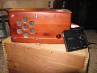
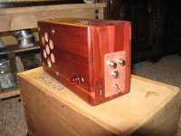
Here's a little project amp, built for my daughter's room. First start-to-finish design and build for me, it was a lot of fun!
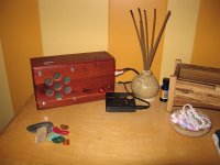
I wanted something REAL small, to sit on the dresser. It didn't need too much volume, though in the end it's got plenty. It's made with mostly recycled parts and I feel makes a pretty easy, not to mention cheap, first project.
About the circuit...
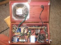
Power supply is based on tid-bits I've used here and there. The back to back wall-wart transformers are nice and cheap, as is the voltage doubler, given access to caps. These came from a t.v. and a computer PSU (both shot, of course). It puts out ~ 280 vdc under load. Pretty sweet for the price, if you ask me. I'll definitely use this in the future for tube stompboxes.
The amplifier is really simple. A self-driven 12au7 with grounded cathodes.
That's about it. I did fiddle with the input impedance to accommodate both headphone-out, and 1/4in guitar out (it doubles as a teeny guitar amp, and sounds quite good with a clean boost or overdrive unit in front...)
The OPT is garbage and not really ideal, but is sooo small, so it fits in the case. Bottom line is, this amp sounds WAY better with a larger speaker, and a proper OPT. There isn't a volume control, that is up to the device running through it.
SO, I'm posting this as both a potential project for others ( I feel like it's pretty unique ) as well as for critique/suggestion. This was designed pretty seat-of-the-pants style, and could almost certainly use improvement circuit-wise.
Here are my initial questions
Only 60vdc on the first plate? Is that right? Plate #2 is full voltage - 280 or so.
After about 5 minutes of duty (Prior to installing the fan) the volume dropped, and the signal became quite distorted. What in there was responding to heat in that way? OPT, PT's, tube, all seemed within temp range. Certainly, nothing way out of line, as far as I could tell. Fan takes core of it, but is a little whiny, which I hate, esp. on an otherwise dead quiet amp.
Anyway, attached are some images, for your viewing pleasure! (pictured with a truly dead technology, the Minidisc!!!)
take it easy,
tyler
My first post, hope it's a good one!
Here's a little project amp, built for my daughter's room. First start-to-finish design and build for me, it was a lot of fun!
I wanted something REAL small, to sit on the dresser. It didn't need too much volume, though in the end it's got plenty. It's made with mostly recycled parts and I feel makes a pretty easy, not to mention cheap, first project.
About the circuit...
Power supply is based on tid-bits I've used here and there. The back to back wall-wart transformers are nice and cheap, as is the voltage doubler, given access to caps. These came from a t.v. and a computer PSU (both shot, of course). It puts out ~ 280 vdc under load. Pretty sweet for the price, if you ask me. I'll definitely use this in the future for tube stompboxes.
The amplifier is really simple. A self-driven 12au7 with grounded cathodes.
That's about it. I did fiddle with the input impedance to accommodate both headphone-out, and 1/4in guitar out (it doubles as a teeny guitar amp, and sounds quite good with a clean boost or overdrive unit in front...)
The OPT is garbage and not really ideal, but is sooo small, so it fits in the case. Bottom line is, this amp sounds WAY better with a larger speaker, and a proper OPT. There isn't a volume control, that is up to the device running through it.
SO, I'm posting this as both a potential project for others ( I feel like it's pretty unique ) as well as for critique/suggestion. This was designed pretty seat-of-the-pants style, and could almost certainly use improvement circuit-wise.
Here are my initial questions
Only 60vdc on the first plate? Is that right? Plate #2 is full voltage - 280 or so.
After about 5 minutes of duty (Prior to installing the fan) the volume dropped, and the signal became quite distorted. What in there was responding to heat in that way? OPT, PT's, tube, all seemed within temp range. Certainly, nothing way out of line, as far as I could tell. Fan takes core of it, but is a little whiny, which I hate, esp. on an otherwise dead quiet amp.
Anyway, attached are some images, for your viewing pleasure! (pictured with a truly dead technology, the Minidisc!!!)
take it easy,
tyler
Attachments
Not sure on optimum value, but this one is really low primary resistance. That is another question I have, as a matter of fact- how exactly does one go about figuring that value, both the optimum for the tube, ant the actual impedance of the transformer, given DCR.
thanks for looking, tyler
thanks for looking, tyler
Also, sorry for being a forum "noob" so-to-speak, but how the heck to I edit a prev. post, I need to rotate the first image!
You only have a limited time to edit a post (30 min IIRC).
I rotated the drawing for you and fixed the diodes while i was at it.
dave

A output tranny with 20k/8 ohm or more common 10k/4 ohm with 8 ohm load will net the most power out of a single section of an 12au7 which will come in at a little under half a watt. Needs to be a good tranny with high primary inductance to get any bass lower than 100hz though. Your probably killing your output section. It shouldn't be ran at higher than 8.5mA with that voltage across it to keep it within spec. That means a voltage around 11 volts on the cathode. The cathode resistor needs to be at least 1.2k.
Last edited:
Nice, I;d change that 100K load resistor to something more sensible though if you want less distortion, that is if that 60V Va of first stage worries you. Try ~20K or so for starters, reduce cathode resistor of first stage to 680R. measure or calculate current through first stage them, measure cathode to anode voltage and report back with the results if you need more help tweaking your amplifier.
Lower load resistances generally result in more distortion, not less.Nice, I;d change that 100K load resistor to something more sensible though if you want less distortion,
I guess I was unclear: within confines of avaliable B+ it is the load that sets the loadline. OP has mentioned that his readings show Vc-a = 60V, which is quite far from the center, which should be somewhere around 135V. Operating a tube that far from the middle of the loadline usually (not necessarily always ! but do check datasheet for 12AU7 if you're unfamiliar with this tube and you'll surely notice that where you end up with 60V on anode is hardly the "sweet spot") results in more distortions, as curves are either "bunched up" or "spread out", the further you move towards each extreme.
I suggested replacing 100K resistor with lower one because this is 12AU7 (ECC82) we're talking about, it has internal resistance of ~7K, 14x times lower than anode resistance value, so 100K load is waaaaay too large for it. Lowering the load and adjusting cathode resistor accordingly will both change the slope of the loadline to increase the current (said tube wants lots of current to operate on more linear portion od its dynamic curve, which of course means is less distortion) and move the operating point towards the center of new loadline, again reducing distortion.
Your remak is correct when certain conditions are met (= that the operating point remains in same spot and you only rotate the loadline around it), however I am suggesting to change those conditions as well") If those condition aren't met, higher load can cause more distortion just as well as smaller one, it all depends on specific situation.
If those condition aren't met, higher load can cause more distortion just as well as smaller one, it all depends on specific situation.
I suggested replacing 100K resistor with lower one because this is 12AU7 (ECC82) we're talking about, it has internal resistance of ~7K, 14x times lower than anode resistance value, so 100K load is waaaaay too large for it. Lowering the load and adjusting cathode resistor accordingly will both change the slope of the loadline to increase the current (said tube wants lots of current to operate on more linear portion od its dynamic curve, which of course means is less distortion) and move the operating point towards the center of new loadline, again reducing distortion.
Your remak is correct when certain conditions are met (= that the operating point remains in same spot and you only rotate the loadline around it), however I am suggesting to change those conditions as well
If those condition aren't met, higher load can cause more distortion just as well as smaller one, it all depends on specific situation.Cool... i've got some OPTs with that impedance... if it was a tweeter amp, the bottom end would be a no care...
You have any 12B4A's in your stash? Another candidate for 20k trannies.
Jeff
Wow, thanks everyone for the input. I'm pretty new at this, and need all the help I can get... So, here's what I did with the load resistor, set it at 33k originally, but (and correct me if I'm wrong) had the cathode resistance too high? Had high voltage, but low current..is that right? I think initially, the cathode resistance was 2k. Here's the deal with this thing: started out building it around a 12at7, which I do know has higher internal resistance, but now that I think about it, not enough to warrant 100k. I spent some time actually comparing my design to the 12au7 datasheet, and it's all wrong. The sections are unbalanced, which (i think) explains the insane oscillation when I tried to tie the cathodes. At ~ 270 on the plates, the grid should be at ~ -10v, so lower grid "bias" resistors, and the cathodes need to be set for ~ 10mA... Is that approximately reasonable?
I need to go read more about cathode biasing. Oh yeah, and everything else.
Really, thanks folks for your input, it will not be squandered!
tyler
I need to go read more about cathode biasing. Oh yeah, and everything else.
Really, thanks folks for your input, it will not be squandered!
tyler
You have any 12B4A's in your stash? Another candidate for 20k trannies.
Not many. Saving those for a pre-amp for now.
dave
At ~ 270 on the plates, the grid should be at ~ -10v, so lower grid "bias" resistors, and the cathodes need to be set for ~ 10mA... Is that approximately reasonable?
Um, I'm not sure if we're using same terminology. My suggestion above is quite conservative, but nevertheless way closer to most linear portion of operation compared to where you have it now.
If you feel like experimenting, try a smaller cathode resistor (330R) or high Vf LED diode (Vf = 2-3V, namely blue, white, possibly amber and bright green colors) in place of my previous suggestion. These will bias tube even better, at the expense of somewhat larger dissipation and consequently shorter lifespan (all suggestions listed are still well within maximum allowed dissiaption though !).
Linearity generally improves as you move away from the centre, towards hot bias. In this case (as for most triodes) centre biasing would make the distortion empirically worse (although it might sound just as pleasing to the ear; you never can tell with these things!). For the lowest distortion you want a high resistance load and a warm bias- which is exactly what he has now- provided of course that the input signal is never large enough to cause clipping, which is unlikely with an MP3 player and that potential divider on the front end.I guess I was unclear: within confines of avaliable B+ it is the load that sets the loadline. OP has mentioned that his readings show Vc-a = 60V, which is quite far from the center,
Of course, it all a bit of a moot point since this is not exactly a numbers-driven, low-distortion amp overall!
Last edited:
Not sure on optimum value, but this one is really low primary resistance. That is another question I have, as a matter of fact- how exactly does one go about figuring that value, both the optimum for the tube, ant the actual impedance of the transformer, given DCR.
thanks for looking, tyler
You ignore the DCR, as an ideal xfmr would have no DCR: it's a bug, not a feature. Given that, xfmr designers do their best to make the DCR as low as possible, much lower than the primary inductive reactance, which is, by far, the most important feature.
As for figuring tube loads: Loadlines, loadlines, loadlines (Scroll down just a bit; there's a five part series on loadlines listed in the extreme, right-hand column.) Loadline analysis works both for voltage gain stages and power stages. Given the very nature of hollow state, there really is no other way to design a hollow state amplifier.
- Status
- This old topic is closed. If you want to reopen this topic, contact a moderator using the "Report Post" button.
- Home
- Amplifiers
- Tubes / Valves
- Tabletop 12au7 Amp