Hi,
Let me precise then, the output DC potential needs to be the voltage at Iref PLUS at least the full signal swing developed into the impedance of the I/U converter.
Obviously, if the I/U conversion is done via resistors tied to Iref then this condition is always fullfilled by design.
If using some form of common base/gate/grid circuit for the conversion then the voltage on the output must be set so this condition is fulfilled under all conditions.
Ciao T
This means Vref should be 1,7V when going the 2mA route. So running the DAC outputs just above this is what you recommend.
Let me precise then, the output DC potential needs to be the voltage at Iref PLUS at least the full signal swing developed into the impedance of the I/U converter.
Obviously, if the I/U conversion is done via resistors tied to Iref then this condition is always fullfilled by design.
If using some form of common base/gate/grid circuit for the conversion then the voltage on the output must be set so this condition is fulfilled under all conditions.
Ciao T
Hi,
Note that one of your I/U solutions inverts polarity and the other does not, make sure to correct for that in your system when comparing.
Ciao T
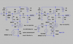
Here are two possible "el cheapo"/no OPT-versions that tries the theories.
Note that one of your I/U solutions inverts polarity and the other does not, make sure to correct for that in your system when comparing.
Ciao T
Vref at the DAC becomes Vdd/3.
Hey T,
I guess you mean "voltage at Iref(pin7)" ?
If so the ideas above need reworking as Vref has to be higher. With 2mA/150ohm, swing will be 300mV ptp giving min 2V for Vref.
Last edited:
Hi,
Yes. Philips uses Vref as the voltage at a resistor junction feeding ultimatly Iref, which is Vdd/2 in the standard app note schematic.
As Iref is actually a voltage imput (with parasitic appx. 11K resistor) I treat it as such and use Vref as designating the voltage at that point.
Ciao T
Hey T,
I guess you mean "voltage at Iref(pin7)" ?
Yes. Philips uses Vref as the voltage at a resistor junction feeding ultimatly Iref, which is Vdd/2 in the standard app note schematic.
As Iref is actually a voltage imput (with parasitic appx. 11K resistor) I treat it as such and use Vref as designating the voltage at that point.
Ciao T
Hi,
Yes, basically. The various relationships between currents are set out in the datasgeet actually.
Ciao T
Aha, so one could as well add Vdd*0,33 directly at Iref to get the wished for 2mA Ifs. Or feed Iref with Vdd*0,67 through a R4 of 11k.
Yes, basically. The various relationships between currents are set out in the datasgeet actually.
Ciao T
Revintage, you can check my previous post concerning applying a voltage directly. For me it gives the best results. I hoped I could "crank up" the voltage in my setup using the trimmer I implemented to set precisely that voltage, but the range is too small (+/-0.2V) and voltage needs to be doubled. I will adapt it when my new discrete version of RBroer's I/V is finalised.
After that (in a month or so) I will try one of your tubed outputs to compare!
For a low noise voltage, I believe the use of a low noise opamp with an "over-filtered" R-divider reference voltage would be the easiest way. Thorsten gave some useful info around Vref in the past (search on kuei / TDA1545):
http://www.diyaudio.com/forums/digital-source/65288-tda1545a-vref-capacitor.html#post737001
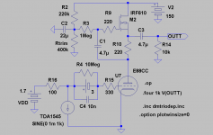
Attached my experiment-platform")
After that (in a month or so) I will try one of your tubed outputs to compare!
For a low noise voltage, I believe the use of a low noise opamp with an "over-filtered" R-divider reference voltage would be the easiest way. Thorsten gave some useful info around Vref in the past (search on kuei / TDA1545):
http://www.diyaudio.com/forums/digital-source/65288-tda1545a-vref-capacitor.html#post737001
Attached my experiment-platform
Attachments
Hi,
For Solid State I'd probably use the Burr Brown OPA860/861 adapted instead of the OPA660 circuit that was discussed here before.
Thorsten, would you go for an opamp solution over a discrete solution??
I will try a tubed output (I do have some E88CC an other lying around) anyway, when I finalise what I started (trying to get rid of the bad habit to startmultiple things without ever finalising
)Discrete super low noise shunt regulator setting the voltage.
Any hints on what the advantage would be to go shunt? I believe the reference voltage applied directly to the Iref-pin doesn't even need to be low impedance, as long as it is super clean.
Thank you for your inputs!
I just looked at the data sheet of the OP660, it is not really an ordinary opamp...
Last edited:
Hi,
No, of course not. The OPA860/861 is not a traditional Op-Amp.
The reference voltage does get applied to some switched circuitry, based on internal design. Also, a shunt can be made to have very low noise and very good ripple/noise rejection.
Ciao T
Thorsten, would you go for an opamp solution over a discrete solution??
No, of course not. The OPA860/861 is not a traditional Op-Amp.
Any hints on what the advantage would be to go shunt? I believe the reference voltage applied directly to the Iref-pin doesn't even need to be low impedance, as long as it is super clean.
The reference voltage does get applied to some switched circuitry, based on internal design. Also, a shunt can be made to have very low noise and very good ripple/noise rejection.
Ciao T
Yes, I saw it Looking at the data sheet and trying to digest the part around
2K2 / 392Ohm and the 500Ohm trimmer. Probably I'm the only one to admit I never saw that strange transistor symbol before... The voltage at pin two of the OPA660 should be at 2/3 Vcc, but I don't see how it would get there.. for me it is at Gnd. Shouldn't Pin 3 not be connected to 2/3 Vcc?
http://www.diyaudio.com/forums/digital-source/16323-opa660-i-v-5.html#post191875
Looking at the data sheet and trying to digest the part around 2K2 / 392Ohm and the 500Ohm trimmer. Probably I'm the only one to admit I never saw that strange transistor symbol before... The voltage at pin two of the OPA660 should be at 2/3 Vcc, but I don't see how it would get there.. for me it is at Gnd.
Shouldn't Pin 3 not be connected to 2/3 Vcc?http://www.diyaudio.com/forums/digital-source/16323-opa660-i-v-5.html#post191875
I need to think and search more before posting...
http://www.diyaudio.com/forums/digital-source/16323-opa660-i-v-6.html#post194250
But still digesting and reading that thread!
Next RS-order these will be added.
860 or 861? The 860 costs double of the 861
@revintage:
I hope you don't mind we talk also about other topologies and that you don't have the feeling I'm highjacking your thread.. otherwize, just say so.
Best,Berny
Hi,
The 860 has a build in buffer that ain't so great.
So may as well buy 861 and twice as many.
Best way to think of these is as bipolar transistors with Vbe = 0V and no need for powersupply.
So, collector is output for common base and/or common emitter circuits, for followers emitter is output, base is input and collector is to ground.
Of course, if your supply is single voltage you need to provide suitable offsets.
So, the idea of the original I/U is to have the base linked to the DC Voltage you want to appear on the DAC Output, which is linked to the Emitter Input. Collector to ground via the I/U resistor, plus apply a suitable offset somewhere so you get 0.5 Supply voltage on the I/V resistor. In this case you would also have to make a low impedance halve supply node for the buffer.
The basic idea (for TDA1541 courtesy of Pedja Rogic) is here:
BTW, the principle is essentially the same as the discrete I/U circuits you have been playing with... Just much easier to work with and quite low noise.
Ciao T
860 or 861? The 860 costs double of the 861
The 860 has a build in buffer that ain't so great.
So may as well buy 861 and twice as many.
Best way to think of these is as bipolar transistors with Vbe = 0V and no need for powersupply.
So, collector is output for common base and/or common emitter circuits, for followers emitter is output, base is input and collector is to ground.
Of course, if your supply is single voltage you need to provide suitable offsets.
So, the idea of the original I/U is to have the base linked to the DC Voltage you want to appear on the DAC Output, which is linked to the Emitter Input. Collector to ground via the I/U resistor, plus apply a suitable offset somewhere so you get 0.5 Supply voltage on the I/V resistor. In this case you would also have to make a low impedance halve supply node for the buffer.
The basic idea (for TDA1541 courtesy of Pedja Rogic) is here:

BTW, the principle is essentially the same as the discrete I/U circuits you have been playing with... Just much easier to work with and quite low noise.
Ciao T
Hi,
That was adapted for use with TDA1541 in that thread...
Ciao T
Yes, I saw it
2K2 / 392Ohm and the 500Ohm trimmer. Probably I'm the only one to admit I never saw that strange transistor symbol before... The voltage at pin two of the OPA660 should be at 2/3 Vcc, but I don't see how it would get there.. for me it is at Gnd.
http://www.diyaudio.com/forums/digital-source/16323-opa660-i-v-5.html#post191875
That was adapted for use with TDA1541 in that thread...
Ciao T
I hope you don't mind we talk also about other topologies and that you don't have the feeling I'm highjacking your thread.. otherwize, just say so.
Na, still learning the digital lingo. So I gain knowledge from every post in this sandy part of audio
.Hi,
Gave the datasheet a deeper look and have now found out that it is all there on how to calculate Ifs etc.
Their 2mA setup has a "voltage at Iref"=1,67V and Vref of 3,34V(2/3Vdd).
Is there any sonic advantages of keeping Vref just so high above "voltage at Iref" that full swing is allowed, against the of Philips choosen Vref=3,34V(2/3Vdd)?
Hopefully Vref isn´t that critical if we´re above the 1,67V+swing value.
Let me precise then, the output DC potential needs to be the voltage at Iref PLUS at least the full signal swing developed into the impedance of the I/U converter.
Gave the datasheet a deeper look and have now found out that it is all there on how to calculate Ifs etc.
Their 2mA setup has a "voltage at Iref"=1,67V and Vref of 3,34V(2/3Vdd).
Is there any sonic advantages of keeping Vref just so high above "voltage at Iref" that full swing is allowed, against the of Philips choosen Vref=3,34V(2/3Vdd)?
Hopefully Vref isn´t that critical if we´re above the 1,67V+swing value.
Last edited:
Hi,
Depends what you do with Vref (Philips) and how much swing you need.
IIRC the TDA1545 can go to within about a volt of the supply rail and down to around V(Iref-pin).
Ciao T
Is there any sonic advantages of keeping Vref just so high above "voltage at Iref" that full swing is allowed, against the of Philips choosen Vref=3,34V(2/3Vdd)?
Depends what you do with Vref (Philips) and how much swing you need.
IIRC the TDA1545 can go to within about a volt of the supply rail and down to around V(Iref-pin).
Ciao T
Hi T,
Obviously I didn´t make myself clear. Or maybe I don´t speak Digitalian good enough. Let´s rephrase:
Voltage at Iref 1,67V in both cases.
Vdd=5V in both cases.
Rload 100ohm in both cases.
Voltage at DACout 2V(via Rload) in the first case.
Voltage at DACout 3,4V(via Rload) in the second case.
No problem with full swing in either case.
So will there be any sonic advantages to use the first before the second case?
Obviously I didn´t make myself clear. Or maybe I don´t speak Digitalian good enough
. Let´s rephrase:Voltage at Iref 1,67V in both cases.
Vdd=5V in both cases.
Rload 100ohm in both cases.
Voltage at DACout 2V(via Rload) in the first case.
Voltage at DACout 3,4V(via Rload) in the second case.
No problem with full swing in either case.
So will there be any sonic advantages to use the first before the second case?
Hi,
The DAC is absically a current source. As long as your signal stays reasonably well away from limits there should not be any change nor have I observed any...
If anything - centering the output within the available range should be best, at leats in theory.
Ciao T
So will there be any sonic advantages to use the first before the second case?
The DAC is absically a current source. As long as your signal stays reasonably well away from limits there should not be any change nor have I observed any...
If anything - centering the output within the available range should be best, at leats in theory.
Ciao T
- Status
- This old topic is closed. If you want to reopen this topic, contact a moderator using the "Report Post" button.
- Home
- Source & Line
- Digital Line Level
- Output level of TDA1545