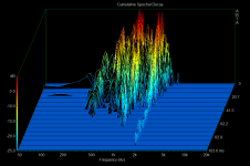
More testing last night had me thinking that something is going on that I didn't consider, so I pulled one of the woofers and mounted the accelerometer on the central brace to see what was happening there. Turns out this was "flapping like a sheet in the wind" with resonances all over the lower frequency range - nothing above 250Hz. This brace is straight from front to back with large cut-outs for the passage of air and I really didn't think about it when I put it in. Turns out that every part of the box needs to be looked at, just because it is inside the box doesn't mean it's immune to resonance.
This brace is also notched for the woofers - the idea being to squirt on a blob of silicone to "anchor" the woofer magnets to the brace on final assembly. Right now the magnets are just touching the brace and let me assure you - this is NOT a good thing.
First thing I did was put a strip of rubber between the magnets and the brace and measured again. A large improvement with the elimination of quite a bit of the "hash" that Dave commented on above.
So, cleaner looking resonance but still too low. I need to brace the brace
I cut two braces to fit and glued them in between the woofers:
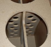
I'll need to let the glue cure overnight before I can put the woofers back in.
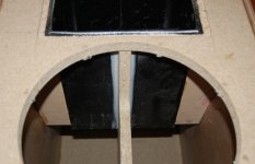
I also cut the sub baffle for the midrange box and put that in:
This brace is also notched for the woofers - the idea being to squirt on a blob of silicone to "anchor" the woofer magnets to the brace on final assembly. Right now the magnets are just touching the brace and let me assure you - this is NOT a good thing.
First thing I did was put a strip of rubber between the magnets and the brace and measured again. A large improvement with the elimination of quite a bit of the "hash" that Dave commented on above.
So, cleaner looking resonance but still too low. I need to brace the brace
I cut two braces to fit and glued them in between the woofers:

I'll need to let the glue cure overnight before I can put the woofers back in.
I also cut the sub baffle for the midrange box and put that in:

The magnet touching the holey brace is not a bad thing. The purpose of that brace is to carry the driver vibration thru to the rest of the box so that the load is shared instead of concentrated in the baffle. It needs to be very strong & stiff and capable of handling the load.
Your execution did have me wondering. Any brace this large will itself need bracing even if made of overkill material -- we found this the case in the Fonken167 which has much less load. You have used chipboard IIRC which is not up to the task . And too many voids make it worse. If i were you i'd rip it out and replace it with 18mm plywood, as well as horizontal braces front to back to help carry the load and to keep the brace stiff at its place of maximum load. In extreme cases, the joins can be gussetted (in all 4 corners) with a stiff hardwood such as oak.
Perhaps a bit late in the design, but with 2 woofers, putting one on the back and taking advantage of the active vibration cancelation of push-push would have been a good idea.
We have always taken this approach with any big woofers we have used and encountered no problems.
dave.
The magnet touching the holey brace is not a bad thing. The purpose of that brace is to carry the driver vibration thru to the rest of the box so that the load is shared instead of concentrated in the baffle.
Ah Dave, maybe my meaning wasn't clear: the magnets were making intermittent contact with the brace (bad!) and when I added the strips of rubber they achieved full contact (good!). Not being especially new to this, I knew (and planned for) the magnets to be supported by the brace.
The particle board I used is stiffer and lighter than MDF and tearing it out at this point is not on the schedule. It can be effectively braced and I feel it is now with the addition of the two lateral braces and the installation of the midrange box.
Mounting the woofers opposed is a nice option but it is not as pretty as two up front like this, regardless of the consequence.
Yes i did misinterpret. Getting the right depth is tricky, intermittent contact is a very bad thing 
Pretty i don't know, impressive (in a male testosterone, mine is bigger than yours way), yes.
When i do something like this the 2 woofers would be on the side, but that is precluded by the innovative wall construction
dave
Pretty i don't know, impressive (in a male testosterone, mine is bigger than yours way), yes.
When i do something like this the 2 woofers would be on the side, but that is precluded by the innovative wall construction
dave
(in a male testosterone, mine is bigger than yours way), yes.
When i do something like this the 2 woofers would be on the side, but that is precluded by the innovative wall construction
To make the best use of these woofers they need to be in a big box so putting testosterone aside, I like the way they both look up front. Sidewall mounting is never an option for me.
You know I'm all about the beautiful things Dave.
4 resonances... low enuff Q that they moosh together almost... all the stuff circa an octave or 2 above the XO will be VERY hard to excite, so the most worrisome one is the Lowest even thou not the highest it also has the lowest Q. They dissipate much more quickly now.
Does ARTA (?) have the ability to get more downward resolution, and switch the z=axis to much more useful units of periods?
dave
Does ARTA (?) have the ability to get more downward resolution, and switch the z=axis to much more useful units of periods?
dave
Arta has another presentation called burst decay and I'm going to use that from now on. One of the problems is that all measurements are relative to their highest peak and Arta puts that as 0db on the plot. You look and see three plots for three measurements and the output for each could be 10db in the difference, but they look the same on the plot. It seems to be impossible to change that in Arta.
I went back and redid some measurements on the compact TL and also on my older 3-ways for consistent comparison.
First is my older 3-ways, broadest side panel:
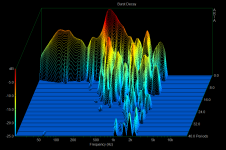
It is surprising just how bad this is, considering the panel is 5/8" MDF laminated to 1/2" particleboard plywood with silicone between the layers - my "constrained layer" damping method.
Next the compact TL:
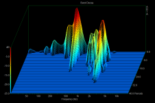
Why it is so strong at 500Hz is beyond me.
Last is my latest measurement of the new three way:
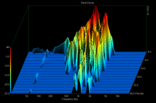
I like the burst decay presentation better as it is cleaner.
First is my older 3-ways, broadest side panel:

It is surprising just how bad this is, considering the panel is 5/8" MDF laminated to 1/2" particleboard plywood with silicone between the layers - my "constrained layer" damping method.
Next the compact TL:

Why it is so strong at 500Hz is beyond me.
Last is my latest measurement of the new three way:

I like the burst decay presentation better as it is cleaner.
Those are much better John. With periods you can see how many cycles it takes for a frequency to decay. A direct relation to the waveform.
I pot those up as blink comparisons.
I will comment later
Panel Tests
dave
I pot those up as blink comparisons.
I will comment later
Panel Tests
dave
Hi okapi,
The silicone acts as a glue to more rigidly hold the accelerometer in place and the results are actually cleaner once it hardens as opposed to just holding the device on with duct seal. Either way (silicone or duct seal) show the same resonances.
What I am coming to appreciate is how complex a box is and how truly difficult it is to effectively reduce vibration. In the measurements, there will be different resonances from other panels mixed in (since they are all connected) also overtones of these resonances show up and are clearly seen in my last plot.
Also I would like to develop a way to mechanically isolate the driver frame from the enclosure. I'm convinced that much of what I'm seeing on the measurements are direct mechanical contribution from the drivers.
I have pulled one of the woofers to apply some damping material. On the side I used a rubberized asphalt membrane (ice and water shield that I bought 3 years ago for a repair on my roof - it has lost much of its adhesive quality so in a method that Cal would recognize, I "torched" it on using my propane torch ) on the side panel and heavy commercial carpet with a plastic/hard rubber backing for the top (bottom actually, but top in the pic) panel:
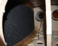
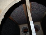
The carpet is adhered with silicone and I need to give that a few hours to cure before I put the woofer back in for testing.
The silicone acts as a glue to more rigidly hold the accelerometer in place and the results are actually cleaner once it hardens as opposed to just holding the device on with duct seal. Either way (silicone or duct seal) show the same resonances.
What I am coming to appreciate is how complex a box is and how truly difficult it is to effectively reduce vibration. In the measurements, there will be different resonances from other panels mixed in (since they are all connected) also overtones of these resonances show up and are clearly seen in my last plot.
Also I would like to develop a way to mechanically isolate the driver frame from the enclosure. I'm convinced that much of what I'm seeing on the measurements are direct mechanical contribution from the drivers.
I have pulled one of the woofers to apply some damping material. On the side I used a rubberized asphalt membrane (ice and water shield that I bought 3 years ago for a repair on my roof - it has lost much of its adhesive quality so in a method that Cal would recognize, I "torched" it on using my propane torch


The carpet is adhered with silicone and I need to give that a few hours to cure before I put the woofer back in for testing.
Last edited:
Hi okapi,
The silicone acts as a glue to more rigidly hold the accelerometer in place and the results are actually cleaner once it hardens as opposed to just holding the device on with duct seal. Either way (silicone or duct seal) show the same resonances.
I don't believe silicone ever really hardens. But i guess the argument you are making is that the silicone and duct seal likely have different resonances and because your measurements are the same with both, the affixing mechanism is not contributing to your measurement. Seems reasonable, but if it were me (and it is not) , I would want to quantify its contribution.
I do like the damping approach the only trade off is added mass. Once the mass starts moving it is more difficult to get it to stop. Membrane roofing is very useful stuff and so easy to work with.
My dream damping mechanism involves external bracing. I would build a fairly standard box with internal bracing, then I would surround all the walls with 0.5 to 1 inch of felt. The felt would then have stiff (aluminum?) panels placed over it that would be externally clamped. They would literally be clamps in the sense that you could adjust the pressure. To most eyes it would be ugly but i think i would love it.
I've noticed the pace of your postings for this project has fallen off - i guess you are human after all
I don't believe silicone ever really hardens. But i guess the argument you are making is that the silicone and duct seal likely have different resonances and because your measurements are the same with both, the affixing mechanism is not contributing to your measurement. Seems reasonable, but if it were me (and it is not) , I would want to quantify its contribution.
I would rather use a more rigid glue, like epoxy to mount the device but I need to be able to remove it without damaging it or the speaker. Silicone does get hard enough to effectively transfer the vibration from the panel to the unit, especially as it is squished out to the thickness of paper. in any case, panel resonances swamp any contribution from the silicone - it would be completely buried.
I am at the testing stage and it takes time to try different things. I have decided to investigate different methods of vibration control on this box, to deepen my understanding of the phenomenon before moving on to its brother.
As for me being human, well the jury is still out on that one...
It's not an exaggeration to say that I have a lot of projects happening, simultaneously - I dabble in others while I wait for silicone to dry or something like that. Also the need to work for a living to pay for this rather costly hobby eats up a fair bit of my time
Last edited:
I've put the woof back in and taken another measurement:
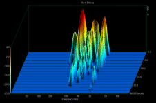
TBH I didn't put much faith in that thin layer of damping but once again I've been proven wrong. Much improved decay time without any bad influence on the resonant freq.
Looking at the plot I interpret it as 2k for the panel the accelerometer is mounted on, I see 1k and that is almost certainly the back panel, which I tested earlier and has a very strong and singular 1k resonance.
The 500Hz is still a stumper though, as no panel anywhere on the speaker has such a low resonance (similar to the compact TL). Could it be an overtone?
I would rather use a more rigid glue, like epoxy to mount the device but I need to be able to remove it without damaging it or the speaker.
What about hot melt glue?
Update:
Just found an article on temporary mounting of accelerometers. Recommended adhesives are hot melt glue or beeswax. No waiting for glue or silicon to set, too.
Last edited:
I have pulled one of the woofers to apply some damping material. On the side I used a rubberized asphalt membrane (ice and water shield that I bought 3 years ago for a repair on my roof -
Is that the stuff you can buy at your local lumber store? I think it is a self stick rubber membrane that they call an ice dam. Typically it is applied to the last 12" or so to the bare wood on the roof to prevent water from wicking up under the shingles.
I was thinking of trying that on my own 3-way. How does that compare with something like Damplifier Pro?
What about hot melt glue?
Good idea! I'll try it

I was thinking of trying that on my own 3-way. How does that compare with something like Damplifier Pro?
Everyone who follows my adventures knows that if it has a brand name like "Damplifier Pro" I won't be using it...if it ain't in my garage already, I'll think of something else to use (like ice and water shield).
The 500Hz is still a stumper though, as no panel anywhere on the speaker has such a low resonance (similar to the compact TL). Could it be an overtone?
I put that latest one up in comparison to the earlier one Panel Tests
The higher resonances are much better damped, as is the one at ~350 Hz (BTW i put the lower resonance in the compact TL closer to 400 Hz).
The scary one is the strong resonance introduced at 500 Hz. Unlike the higher ones, this probably has a chance at being excited (what is the planned XO).
Did you do anything else inbetween other than the damping? Any diiferences in the way the removed woofer was reinstalled?
dave
- Status
- This old topic is closed. If you want to reopen this topic, contact a moderator using the "Report Post" button.
- Home
- Loudspeakers
- Multi-Way
- Large 3-ways design / build
