This question is one for the more knowledgable (at least more than me) contributors on this forum.
I have been looking at the RCA Handbook # 20 and it has a microphone / phonograph amplifier (8 watts with 6L6-GC as output tube).
The microphone and tonecontrol are using a 12AX7 and the driver stage has a 6AV6 which according to the tube manuals is the same as 1/2 12AX7.
I never like the idea of using half of a double triode for one channel and the other half for the other channel so will resort to using a full 12AX7 as driver.
Knowing that the 6L6-GC can demand quite a bit of drive when driven in positive grid territory I am thinking if I should use both halves in parallel and adjust the resistor values accordingly. Am a bit reluctant to do this (although it is done in my Ming Da MC34-B) since I have read some observations that when using parallel output tubes it (supposedly?) affects the sound quality.
Gents, (and gals if they are around) please let me know of your opinions,
Thanks, AM.
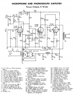
As requested the schematic is attached. One thing that is attracting me to this design is the feedback from the plate rather than the secondary of the transformer. It will need a good transformer but in the Radiotron Handbook this form of feedback is regarded as "very statisfactory" and also Alex Kritic's RH807 has feedback from the plate. This avoids a lot of the phase shift that happens in the transformer and this has a profound effect on the performance at both top and bottom end.
What I am proposing is to leave away the 12AX7 in total but am not too sure if I'll have enough gain in that setup. Am not too keen on going with a long tail design since then we start to run into trouble with heater-cathode voltage levels exceeding max values.
Thanks in advance for your input.
What I am proposing is to leave away the 12AX7 in total but am not too sure if I'll have enough gain in that setup. Am not too keen on going with a long tail design since then we start to run into trouble with heater-cathode voltage levels exceeding max values.
Thanks in advance for your input.
Attachments
The tube driving the 6L6 isn't overly critical. C13 will prevent you from ever driving the 6L6 into "positive grid territory." As soon as the signal becomes that large, the cap will charge up and the outpout stage will distort. Driving the grid positive without distortion requires either an interstage transformer or direct coupling from a low Z source such as a cathode follower. Also, there is absolutely no reason not to share twin tubes between channels. For 9-pins, I would use a 12AU7 as driver, only because it's more robust than the 'AX7 and can drive a smaller grid resistor.
don't know what your intended end use is, but worth noting that the set-up is for a crystal input ie higher voltage than a modern mm cartridge or mike will provide.
In fact, for use with a modern line level source it appears to have PLENTY of gain. Proviso here - I haven't done the math, I'm just looking at the magnitude of values used.
Lots of discussion on this site around the partial feedback / Schade feedback approach with the conclusion that it operates best against a high impedance driver, so a pentode is indicated rather than the triode like the 6AV6. So, a 6AU6 is a more likely candidate.
In short, unless you have a specific requirement to use the voltage amp and driver topology that is shown, there are better alternatives around that would perform better...
First, understand the context- this circuit was meant for cheap and cheesy low end phonographs. Goals are low cost and mass production, not high quality. As Aard points out, the gain structure is set up for the cheapest and poorest quality cartridges, not for modern MMs (or even the MMs of its day).
The feedback is arranged as it is because of the use of the cheapest possible transformer. Driven by a pentode, the distortion would be too high because of the source impedance. The feedback's main purpose here is to reduce the effective plate resistance of the output tube.
The coupling between sections of a 12AX7 is several orders of magnitude lower than the crosstalk from any phono cartridge, i.e., don't worry about it. The thing about paralleled output tubes is nonsense.
Thanks for the replies and pointing out that it was meant for the cheapest possible iron. We can turn that equation around and with good iron the results (omitting the tone control and microphone stage) should be quite good. ( After all the OPT is normally the weakest point and if we can get decent result using this topology with the lowest quality iron then what is waiting for us when using the good stuff?) It is interesting to read in the Radiotron HB (both 3 & 4) that this form of feedback from the plate gives very satisfactory results. And so it should be since we have less issues with phase shift. And the standard second harmonic produced by an OPT is not objectionable. (if I am wrong please correct me, after all I am a newby to hi end tube audio amps)
AM
AM
Thanks for the replies and pointing out that it was meant for the cheapest possible iron. We can turn that equation around and with good iron the results (omitting the tone control and microphone stage) should be quite good. ( After all the OPT is normally the weakest point and if we can get decent result using this topology with the lowest quality iron then what is waiting for us when using the good stuff?) It is interesting to read in the Radiotron HB (both 3 & 4) that this form of feedback from the plate gives very satisfactory results. And so it should be since we have less issues with phase shift. And the standard second harmonic produced by an OPT is not objectionable. (if I am wrong please correct me, after all I am a newby to hi end tube audio amps)
AM
I'm not convinced, it seems to me there are much better more modern designs floating around right here. I grew up in the 1960s and well remember the sound of some of these very inexpensive phonograph amplifiers. I wouldn't bother to replicate those designs even with decent transformers, the designs were just not that good. Instead and for roughly the same money I would recommend Tubelab's simple single ended amplifier. If you want to build it point to point you can do so, this I think would give you a much more predictable end result.
This question is one for the more knowledgable (at least more than me) contributors on this forum.
I have been looking at the RCA Handbook # 20 and it has a microphone / phonograph amplifier (8 watts with 6L6-GC as output tube).
That design is absolutely hideous. I wouldn't bother.
The microphone and tonecontrol are using a 12AX7 and the driver stage has a 6AV6 which according to the tube manuals is the same as 1/2 12AX7.
You see that all the time, and it just ain't so. Take a look at the specs: 12AX7: Pd= 1200mW. 6AV6: Pd= 500mW. That, right there, ougth to tell you that one 6AV6 != 1/2 12AX7. A 6AV6 isn't up to driving a load like a 6L6. You'll probably have slew rate troubles at the high end, and the 6AV6 will roll over and die when that high level transient comes along and forces the 6L6 grid positive. The clipping behaviour on overdirve is going to be simply gawdawful.
I never like the idea of using half of a double triode for one channel and the other half for the other channel so will resort to using a full 12AX7 as driver.
Why? Take a look at the specs again. The capacitances between sections are a fraction of a pF, not big enough to make any meaningful difference until you're approaching VHF.
Am a bit reluctant to do this (although it is done in my Ming Da MC34-B) since I have read some observations that when using parallel output tubes it (supposedly?) affects the sound quality..
There is some controversy over this. Some say it makes a difference; some say it doesn't. Paralleling VTs can help with noise reduction. It's one of those areas where you have to try and see for yourself.
That design is absolutely hideous. I wouldn't bother.
.. some say it doesn't. Paralleling VTs can help with noise reduction.....
Miles
Thanks for chiming in. I've read anumber of your posts and I greatly appreciate your opinions.

On this note - I see you have had a close look int he past at the RH84 / RH807 and also chimed in on the "New KT66 - 6AU6 SE' thread ( http://www.diyaudio.com/forums/tubes-valves/102540-new-kt66-6au6-single-ended.html ) where you did some simulation / calculations. Those two designs (as well as the Tubelab Simple SE and J C Morrison's design with the EF86 as driver) are another couple of designs that I am closely looking at.
I like in particular the local feedback but I am not convinced that I want to use a 12AT7 (ECC81). In addition I would prefer to use a tube which is in current production (e.g. the ECC83 / 12AX7) which is why I did not want to use the 6AV6 in the first place.
Could you be so kind and vent your view on Jorgetronic's KT66 - 6AU6 SE design?
(PS I have also looked at a kit which is for sale on eBait from a Hong kong seller which is using an 12AX7 as driver where the first part is the voltage amplifier and the second part of the 12AX7 is a cathode follower. Got my reservations of having the cathode sitting at the anode potential of the first section since I am concerned about heater - cathode breakdown and longevity of the tube when used in that manner).
Regards, AM

Could you be so kind and vent your view on Jorgetronic's KT66 - 6AU6 SE design?
I don't see anything terribly wrong with that design, and I've seen others that are similar and that work pretty good. The 6AU6 is a dependable work horse that does just about everything well: CCS duty, audio, and RF. It should work as a first project.
Got my reservations of having the cathode sitting at the anode potential of the first section since I am concerned about heater - cathode breakdown and longevity of the tube when used in that manner).
In cases like this, it's common to elevate the heater supply with a DC voltage to keep from busting that Vhk rating. Another possibility is to float the whole heater supply. If there's no connection to ground, then Vhk doesn't matter. I have another project where the whole heater winding was floated for just that reason. I expected lots of hum, but got very little.
In cases like this, it's common to elevate the heater supply with a DC voltage to keep from busting that Vhk rating. Another possibility is to float the whole heater supply. If there's no connection to ground, then Vhk doesn't matter. I have another project where the whole heater winding was floated for just that reason. I expected lots of hum, but got very little.
Besides using a solid state (and then discovering after a number of years that the particular piece of sand is no longer being manufactured) it may be possible to change the implementation (not topology which is pretty good).
Since we work with stereo we could use one tube for the pre-amp part (of both channels) and the other tube for the cathode follower and raise the heater to the dc voltage of the cathode. Only issue one might have is increasing crosstalk (decreasing channel seperation) by having both channels in the same envelope. I think that would be a small price to pay for lowering the potential between heater and cathode.
OK on the 6AU6 being a good workhorse, only thing I don't like is that it is not manufactured any longer so one has to start hunting around for NOS (seems plenty around) and then stocking up for spares.
I have asked for a quote on James iron, OPT's, power transformer and choke which can be re-used in other designs should I want to change the design.
Many thanks, I think this is a serious contender for my project.
AM
I don't see anything terribly wrong with that design, and I've seen others that are similar and that work pretty good. The 6AU6 is a dependable work horse that does just about everything well: CCS duty, audio, and RF. It should work as a first project......
I used to be a HAM starting out with tubes. I prefer this to be my only audio tube project so am spending a lot of time in getting the right SE design. I want to stick to a 6L6-GC / KT66 output stage and I like the feedback from the plate of the output tube.
At this moment it is started to shape up like a choice between this 6AV6 - KT66 design and the RH807 (with the Simple SE as a distant third choice. Fourth fallback is the J C Morrison with the EF89 as a driver tube).
I've decided that I'll be using James iron all around, will make for a good look too.
AM
Lots of discussion on this site around the partial feedback / Schade feedback approach with the conclusion that it operates best against a high impedance driver, so a pentode is indicated rather than the triode like the 6AV6..
Have been doing a bit more research on this. Alex Kitic made some waves with his "RH84" and "RH807" amps which has a lot of happy DIY builders making more than one.
I found reference to this "inverse feedback" on page 29 in the RCA Handbook #17 and it is mentioned that this feedback work best on the output tube being a pentode and has hardly an influence on a triode. I also found some reference that it actually is best to use a triode as driver.
There is also another aspect here at work: the 12AT7 is known for having a lot of 2nd Harmonic distortion. A 807 (or 6L6 for that matter which is the same tube except the 807 has its anode coming out at the top) has a lot of 2nd Harmonic too but because this is out of phase with the 2nd Harmonic from the driver it gets largely cancelled.
This feedback is regarded as very satisfactory in the Radiotron Handbook (both 3 and 4) mainly because it largely negates the effects of a varying speaker load.
At this moment the RH807 is on the cards except I'll be building it with 6L6-GC STR since I have a matched quad of Tung-Sol NIB.
Shame I cannot use the Mullard Re-issue 12AX7 or the RFT 12AU7 that I have here (two of each NIB, purchased as spares for another amp) and will have to buy some 12AT7's.
AM
as a public service, I'll take them 12AU7s and 12AX7s off your hands for a nominal fee....
Schade is the classic article on cathode to grid feedback. Broskie (Tubecad) also does an article on it. Take a look at Shoogs pp design using this feedback. There is a LOT of discussion around it. The consensus is hi Zo driver is best and that indicates pentode.
Yes Alex used triodes. Doesn't mean it was optimal, just that it worked well. I'd look to keep it octal and go with 6SJ7...
You see that all the time, and it just ain't so. Take a look at the specs: 12AX7: Pd= 1200mW. 6AV6: Pd= 500mW. That, right there, ougth to tell you that one 6AV6 != 1/2 12AX7. A 6AV6 isn't up to driving a load like a 6L6.
Hmmm... RCA tube manual # 20 (and other versions too but I just looked this one up) says under 12AX7: (quote) "for characteristics and curves see 6AV6".
If I look at the original 6L6 with 19 Watt anode dissipation and a metal enclosure then by your reasoning/remarks I should not be able to replace a 6L6 with a 6L6-GC STR.
So what if the capacitances are slightly different in the 12AX7 and the anode dissipation is higher in the 12AX7, surely I would be able to replace the 6AV6 with one section of a 12AX7?
Confused.
AM
So what if the capacitances are slightly different in the 12AX7 and the anode dissipation is higher in the 12AX7, surely I would be able to replace the 6AV6 with one section of a 12AX7?
You can probably replace a 6AV6 with one section of a 12AX7. VTs tend to be more "forgiving" than solid state. However, it may not work going in the opposite direction since a 12AX7 may have been biased hotter than a Pd= 500mW.
- Status
- This old topic is closed. If you want to reopen this topic, contact a moderator using the "Report Post" button.
- Home
- Amplifiers
- Tubes / Valves
- 6AV6 => 12AX7 question