Hi All,
Well i finally started my simplese project, and having a few teething problems...
Wired it up with the following Iron.
Edcor CXSE25-8-5K OPT
Edcor xpwr059 wired 350v red to t1-red pin 1&3, brown to 5v t1-yel, red & blk t1-red-yel, 6.3v yellow to t1 green.
Hammond 193H choke wired to L1
The circuit powers up without any undue noises or smells, the tubes glow, and i get some sound. I have double checked the star earthed and the inputs, outputs and transformers have continuity.
I would describe the symptoms as if the pre amp section is working, but the output valves aren’t. Very low output before the sound starts clipping.
I had a quick check of the Anode, no voltage, heaters have 34v on pin 2&7.
Pin 6 has 522v, i thought it was no connection?
I am only using valve rectification; do i need to short SW1 or jumper it in some way to pass the voltage to the Anode? I am hoping this is the issue!
Couldn’t find a testing procedure or FAQ, is there such a thing available.
Any other ideas would be great?
Many Thanks
Ian
The Tubelab Simple SE has lots of gain, and should provide plenty of volume.
I am concerned that you see no voltage on the anode, but 522 volts at pin 6. I believe you are correct - pin 6 should be no connection. How are you counting the pins? Looking at the board from the socket side, pin 6 should be the one right next to the silkscreened lettering "V21" or "V11". Are you certain you aligned the socket keyway properly when assembling the board?
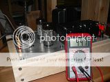
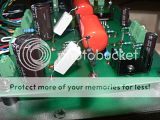
Have you top mounted, or bottom mounted the components? Do you have the means to take and post a digital photo?
You should not need a switch at SW1. That is only required for those who choose to use the solid state rectifiers.
I am concerned that you see no voltage on the anode, but 522 volts at pin 6. I believe you are correct - pin 6 should be no connection. How are you counting the pins? Looking at the board from the socket side, pin 6 should be the one right next to the silkscreened lettering "V21" or "V11". Are you certain you aligned the socket keyway properly when assembling the board?
Have you top mounted, or bottom mounted the components? Do you have the means to take and post a digital photo?
You should not need a switch at SW1. That is only required for those who choose to use the solid state rectifiers.
Thanks TY,
You are of course correct, I was counting the pins incorrectly.
Fresh eyes and some sleep makes all the difference..
So pin 2&7 have 34v and pin 3 has 522v.
I have used an ipod into a passive alps pot to provide test music. But would still expect it to go a lot louder before distorting. It is very quiet.
Are there any test readings that might help diagnose?
In the meantime i will dig out my camera.
Thanks for any suggestions
Ian
Pins 2 & 7 are the heater connections. I think George elevated the heater supply in this design to reduce noise. That doesn't really tell us anything. You might want to check the voltage at pin 8 (cathode), pin 5 (control grid), and pin 4 (screen grid).
There are two good threads around here containing at length discussions of a problem similar to yours. If I can find the threads, I will link to them. In the first case, the builder had inadvertently swapped R15/R16 (220K/100 ohms). In the other case, the builder had drilled out the through-plated holes for the coupling caps, effectively breaking the connection.
You might also want to swap the 12AT7 tube if you have a spare, and double check your wiring around the input connector (especially if you have a volume pot).
Edit: Try reading through these threads, and see if anything appears similar to what you are observing.
Post #55 ~ #142
http://www.diyaudio.com/forums/tube...et-another-simple-se-build-2.html#post1664764
Post #67 ~ #128
http://www.diyaudio.com/forums/tubes-valves/145215-simple-se-build-2.html#post1871152
Last edited:
Thanks again ty,
I forgot to say that the readings i gave for the output tubes were the only ones, all the other pins read 0vdc,
pin1 = 0
pin2 = 34
pin3 = 522
pin4 = 0
pin5 = 0
pin6 = 0
pin7 = 34
pin8 = 0
reading the other threads I double checked the values ofr16,r26,r15,r25 all correct.
No input signal gave r10 & r20 =1.9 vdc each
c11=225v c21=209
But R17 &R27 = 0 I am running 560ohm so should be getting 30-40vdc, any ideas?
Thanks
Ian
pin8 = 0

That's not right. Are you trying to use cathode feedback? If you are, did you connect the output transformer correctly? If not, did you remember to install the jumper across T2-SEC and T3-SEC?
Hi Ty,
Just wired as basic amp without feedback, no CFB or UL.T2-SEC and T3-SEC have jumpers and continuity checked. T3-PRI pin 03= B+ red wire, 02=nc, 01= plate blue wire, same on T2-PRI. I have just taped up the UL wire from the output transformer, does this look ok?
Thanks again
Ian
Just wired as basic amp without feedback, no CFB or UL.T2-SEC and T3-SEC have jumpers and continuity checked. T3-PRI pin 03= B+ red wire, 02=nc, 01= plate blue wire, same on T2-PRI. I have just taped up the UL wire from the output transformer, does this look ok?
Thanks again
Ian
I have used an ipod into a passive alps pot to provide test music. But would still expect it to go a lot louder before distorting. It is very quiet.
Just to check the obvious (doesn't hurt to make sure) do you have the volume on the iPod all the way up? Keep in mind the last 10mm of the volume bar on the iPod goes up in a more logarithmic pattern.
T3-PRI pin 03= B+ red wire, 02=nc, 01= plate blue wire, same on T2-PRI. I have just taped up the UL wire from the output transformer, does this look ok?
No, this won't work and will result in exactly the voltage readings you have. There is no voltage on Pin 4 which results in no cathode current which results in no voltage on pins 1 and 8. The fix is simple. The 02 pin on the PRI connectors MUST be connected to SOMETHING. Jumper it to the plate (01 pin) for triode mode, or connect the UL tap on the OPT to the 02 pin for UL mode.
Hi All,
I am getting on very well with the tubelab SSE, Love the clarity & sound staging. Real improvement on my little ASL Wave 8's.
I wanted to know where to take a feed for a 6.3V, .15A bulb, Can i connect it to T1-GRN 6.3v or will that inject noise into the circuit?
I also have some 6P3S valves kicking about, but am unsure if i can just drop them in place of the 6L6GC's. When using 5AR4, i am getting 458V. With a 5U4G, 434V. I just have the 560Ohm R17&R27. Will this be too much for the 6P3S, the data sheet i have is unclear about the maximum ratings?
Many Thanks
Ian
I also have some 6P3S valves kicking about, but am unsure if i can just drop them in place of the 6L6GC's. When using 5AR4, i am getting 458V.

http://s69.photobucket.com/albums/i43/Ty_Bower/Simple SE/P1110492.jpg
http://s69.photobucket.com/albums/i43/Ty_Bower/Simple SE/P1110495.jpg
Are they 6P3S, or 6P3S-E? I've been told the 6P3S are not particularly impressive, and they may not hold up well under your voltage and current conditions. On the other hand, the 6P3S-E is a very nice tube. I often prefer it myself in my own Simple SE. I would recommend increasing your cathode resistance a bit. I started out with 560 ohms, which was good for KT88 but a bit much for the other tubes. I have since increased it to 810 ohms and all is well.
If you want more options for playing with other types of tubes, maybe this idea will help:
Choke modification for Simple SE
http://i69.photobucket.com/albums/i43/Ty_Bower/Simple SE/chokemod.gif
On the back side of the board, cut the trace between C1 and R2. Ignore my note about the jumper. Add a big (6H ~ 10H) choke between the SW1-O1 terminal and the L1-O2 terminal, as suggested by George. Now you should get just slightly more than 300 volts B+ and you can play with 6V6 type tubes. Your 6P3S should be happy as well, and the very pretty 6L6GA could be tried too.
As far as the rectifier is concerned, I would recommend just staying with a quality old stock 5AR4.
Hi TY,
Thanks for the link, interesting mods. I might even by another PCB, really impressed with the quality and just using a baking tray for a chassis. Will be really nice when finished. I had to use .47 coupling caps as i ordered the wrong size, will this effect the sound much?
I think i will keep the voltage as it is now and buy some more tubes. Do you know if it possible to run an 807 SE by modding the circuit and changing the valve socket? They look so cool with the blue glow and top cap!
I bought some fender style jewel power lights,and wanted to know where to take a feed for a 6.3V, .15A bulb, Can i connect it to T1-GRN 6.3v or will that inject noise into the circuit?
Many Thanks
Ian
I'm glad you enjoyed. I forgot to point out that with the lowered B+, you will likely need to jumper around R14 and R24 (the 10K, 3 watt parts) or else the CCS might not get enough voltage to work at its full potential.
The use of larger coupling caps shouldn't make much of a difference at all. You'll get a lower Fo cutoff point, but it's already pretty low with the stock values. The formula is 1/(2piRC), if I recall, which should put it at ~3 Hz with the stock parts. Doubling the coupling cap will lower the F0 by half to ~1.5 Hz. Pretty much inaudible in any case. There was a discussion around here about using the smallest cap that got the job done, as the grotesquely large caps seemed to rob detail or something. In any case, I'm sure your amp will be fine either way.
Tubes that don't have the standard 6L6 or EL34 pinout are awkward. With the PCB type design, it's impractical to substitute different sockets, add plate caps, etc. Some have done it but I would seek a different platform for such experiments.
I can't comment on your power lamp. Try it and see - it shouldn't hurt anything, assuming you've got sufficient reserve on the 6.3 volt winding.
Hi TY,
I have ordered four nos 6P3S-E's and a couple of nos 5u4g's for the amp. They are really cheap to buy from Europe. I will drop in the 810 ohms resistor, should be a little kinder to the tubes.
I was hoping there might be another SE project that SimpleSE builders could try out using the same hardware, just swap the PCB over. Now that would be awesome, have a PCB that drops into the same chassis, just a different type of output tubes like UX5 type.
I make is sound easy, shows how little I know.
I am very grateful to Tubelab & this forum, i have fumbled together a great amp and learnt a lot on the way.
Next up, a phono stage. I will start a new thread for this one.
Cheers
Ian
I am going to install 810Ohm resistors on the PCB, but what value do i add to the switch to get 560Ohm at the PCB?
http://i69.photobucket.com/albums/i43/Ty_Bower/Simple SE/P1100584.jpg
I just left the 560 on the board, and added another 250 in series with it. If you want to go back to 560, just add a switch that jumpers around the 250.
- Status
- This old topic is closed. If you want to reopen this topic, contact a moderator using the "Report Post" button.
- Home
- More Vendors...
- Tubelab
- simplese trouble shooting