thx for info
isnt 600VA too much for F5 or you will use It with other project
I think when Nelson designed the F5 he didn't go crazy with boutique parts and huge margins of excess capacity. I don't think he ever does. But it sounds great. That said, I don't think you can have too much transformer. However, there is probably a point of diminishing returns. 600VA is about twice what the transformer factory F5 uses.
The toroidy transformer seems like a lot of transformer for the money. I'm wondering if there's a way to get them to the USA for a reasonable cost.
The diodes? Well I guess one could compare the standard silicone bridge rectifier with high speed diodes. I suspect the standard one works okay.
Great price. How is the quality of those transformers?
According to some people on this forum, they deliver excellent stuff.
I will test them in a month or so (when they arrive) and report back here.
I think when Nelson designed the F5 he didn't go crazy with boutique parts and huge margins of excess capacity. I don't think he ever does. But it sounds great. That said, I don't think you can have too much transformer. However, there is probably a point of diminishing returns. 600VA is about twice what the transformer factory F5 uses.
The toroidy transformer seems like a lot of transformer for the money. I'm wondering if there's a way to get them to the USA for a reasonable cost.
The diodes? Well I guess one could compare the standard silicone bridge rectifier with high speed diodes. I suspect the standard one works okay.
In the original (and commercial) F5 you have to strike a balance between cost and search for optimal performance. As a diy guy, you can spend as much as you like.
Nelson himself has expressed his opinion that (if money and size is no object) too large a tranny and capacity in a PSU does not exist.
It will make the PSU more stable, reliable and quieter when you go for oversize. According to many people, a class A amp does sound a little better with an oversized PSU.
The only real disadvantage is your own health, particularly that of your spinal system...

According to some people on this forum, they deliver excellent stuff.
I will test them in a month or so (when they arrive) and report back here.
If they are as good as Plitron and the cost to ship them is reasonable then they may be a better value.
i bought P.D.'s boards last spring and finally getting around to sourcing parts. found 10 of these for $50 - 11.25"x4.5"x1.25". i'll be using 2 sinks per channel, mounted vertically.
http://cgi.ebay.com/ws/eBayISAPI.dll?ViewItem&item=220487821462&ssPageName=STRK:MEWNX:IT
http://cgi.ebay.com/ws/eBayISAPI.dll?ViewItem&item=220487821462&ssPageName=STRK:MEWNX:IT
Last edited:
How close should those Thermistors be?
Maybe someone has already addressed this, but the thread is sooo loooong!
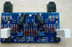
I wonder how close the thermistors should be placed to the power mosfets. I will use an aluminium bar to press the power fets tightly to the heatsinks. Should the 4.7k NTC thermistors be within millimeters of the power fets?
I already soldered 2 of them normally on the board (see photo), but I could lead them away from the pcb to the mosfets, with their legs isolated of course.
How did others solve this?
Maybe someone has already addressed this, but the thread is sooo loooong!
I wonder how close the thermistors should be placed to the power mosfets. I will use an aluminium bar to press the power fets tightly to the heatsinks. Should the 4.7k NTC thermistors be within millimeters of the power fets?
I already soldered 2 of them normally on the board (see photo), but I could lead them away from the pcb to the mosfets, with their legs isolated of course.
How did others solve this?
Attachments
Maybe someone has already addressed this, but the thread is sooo loooong!
I wonder how close the thermistors should be placed to the power mosfets. I will use an aluminium bar to press the power fets tightly to the heatsinks. Should the 4.7k NTC thermistors be within millimeters of the power fets?
I already soldered 2 of them normally on the board (see photo), but I could lead them away from the pcb to the mosfets, with their legs isolated of course.
How did others solve this?
closest you can ;
closer- better tracking
Maybe someone has already addressed this, but the thread is sooo loooong!
I wonder how close the thermistors should be placed to the power mosfets. I will use an aluminium bar to press the power fets tightly to the heatsinks. Should the 4.7k NTC thermistors be within millimeters of the power fets?
I already soldered 2 of them normally on the board (see photo), but I could lead them away from the pcb to the mosfets, with their legs isolated of course.
How did others solve this?
You can put the thermistors on the case of the MOSSFET's (ner the mounting screw) or right adjacent to them. With peter's boards it might be necessary to slip some heat shrink tubing on the leads of the thermistor to prevent accidental contact with the MOSFET leads.
i bought P.D.'s boards last spring and finally getting around to sourcing parts. found 10 of these for $50 - 11.25"x4.5"x1.25". i'll be using 2 sinks per channel, mounted vertically.
http://cgi.ebay.com/ws/eBayISAPI.dll?ViewItem&item=220487821462&ssPageName=STRK:MEWNX:IT
So lucky
I looked at that listing (after it had ended ) and those heatsinks are coming from the same town where I live. Maybe I can drive over and hand the guy $60 and steal them before they ship!!
Beftus, may be you could use them as screws for mosfets mounting.
Good thinking, hadn't thought of that! I don't think it will be a good idea though. There's not much threading left if I account for a washer on top of the MOSFET and thermal foil under the MOSFET. Maybe 2 or 3 turns left...
i bought P.D.'s boards last spring and finally getting around to sourcing parts. found 10 of these for $50 - 11.25"x4.5"x1.25". i'll be using 2 sinks per channel, mounted vertically.
http://cgi.ebay.com/ws/eBayISAPI.dll?ViewItem&item=220487821462&ssPageName=STRK:MEWNX:IT
Doesn't seem like two per channel will do the job for the F5.
Doesn't seem like two per channel will do the job for the F5.
we'll see...
So lucky
. sorry, you snooze you lose.... fire !
i'm confident that they'll be enough. anyone elese care to share?
i have access to lots of cheap drop cut aluminum. a slab of 1/4" thick on the flat side with the MOSFETs and thermal grease sandwich may be necessay.
i'm confident that they'll be enough. anyone elese care to share?
i have access to lots of cheap drop cut aluminum. a slab of 1/4" thick on the flat side with the MOSFETs and thermal grease sandwich may be necessay.
The manual recommends a 6" x 8" piece with 1/4" base and 2" fins per MOSFET as a minimum. That's 96 square inches of fairly heavy heatsink per channel. I guess you could keep adding aluminum until it runs cool enough. However the heat is pretty concentrated from only two MOSFETs so you'll need to devise a solution to spread the heat out fairly quickly.
The manual recommends a 6" x 8" piece with 1/4" base and 2" fins per MOSFET as a minimum. That's 96 square inches of fairly heavy heatsink per channel. I guess you could keep adding aluminum until it runs cool enough. However the heat is pretty concentrated from only two MOSFETs so you'll need to devise a solution to spread the heat out fairly quickly.
i haven't played around with this high level of thermal management before, but let's assume 30-35C above ambient. in the summer months, my house is 24C max and winter 18-20C. add these numbers and we're still under 1/2 of the 150C rated operating temp of the MOSFETs.
the actual square area of my heatsinks are greater than the recommended (50.6" vs 48"), but have shorter fins and less in number. the heatsinks will be mounted with the fins running vertically, and one heatsink per MOSFET. i'll be happy if my thermocouple readings at the heatsink/MOSFET junction is <60-65C.
- Home
- Amplifiers
- Pass Labs
- F5 power amplifier