L/C calculator for those interest
please follow the line have a calculator the the job
http://circuitcalculator.com/lcfilter.htm
please follow the line have a calculator the the job
http://circuitcalculator.com/lcfilter.htm
audio1st said:Hi ElFishi,
I thought this may have been the cause of the heat, I take it that it made no difference?
Thanks for your trouble..
PS, would changing the 680nF output caps to 220nF caps work?
Sorry to disappoint, heat is still there. But I admit I was hoping the same as you did.
You certainly did the math right on the output, but I'm at a loss myself what determines a good balance btn L and C.
The attenuation of an LC-filter does depend however on the serial resistance. It is a second order filter that can display a resonance at the cutoff frequency.
Personally, I don't trust the inductors, that's why I want to have a go at them. I'm sure they work alright, but I'd rather have toroids for the stray EMR.
nrg2009 said:... R14 and R34 (22k) are not in the signal path, but connected to ground? So my question is that if that is true why remove them?
Well, why are they there in the first place? They will lower the input impedance of the amp and there are source that will not like that.
I replaced the tank caps on my board to a total of 7200uF. Now, if I switch off the power, the amp goes on for a second or so and then I sometimes get an ugly screetching sound. Does anyone make the same observation?
nrg2009 said:This I'm sure is a very silly question to the veterans, but since I'm a noob I'll ask it anyway.
I look at the schematic on page 10 of the manual (page 13 of 15 in Adobe) and it seems to me that R14 and R34 (22k) are not in the signal path, but connected to ground? So my question is that if that is true why remove them? are they some sort of snubber?
Thanks
Hi,
They only need to be removed if you place the new input caps pre board and bridge the original location (stealth). This moves R14 & R34 from being in front of the input caps to now being after the input caps, this will then DC couple the input to ground which is biased at approximately 2.5VDC. This DC is multiplied by the gain of the amp to produce about 20vDC at the speaker terminals.
I hope this makes some sense?
If anyone remembers the Sonic Impact stealth mod, you had to remove R01 & R02.. same reason..
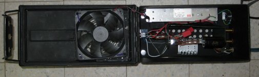
Was it riktw who first mentioned using a 12v fan running at 5v? It is a brilliant solution!
It seems you don't need to move a lot of air to cool the stock heat sink. I put on a tiny 2" fan, just stuck it right on the heat sink with a touch of silicon glue. Although the air movement is scarcely perceptible, the heat sink now barely rises above room temp. It was definitely hot before.
Good going, riktw!
-dr_vega
audio1st said:PS, would changing the 680nF output caps to 220nF caps work?
Did some more pondering.
Don't mistake me for an expert, but I looked up the properties of a LC-lowpass. You can determine the transmission of such a filter as a function of R, L and C.
Now, the output stage of the tripath circuit differs from a simple LC-lowpass and I am not able (for now...) to determine the transmission of such an array. Certainly the resistance, inductance and capacitance of the speakers play a role in the performance of the output.
Attached you find a graph that displays the transmission in dB over the frequency for a simple LC-lowpass. It becomes clear that depending on the resistance the choice of L and C can be better or poorer even if you hit the same cutoff frequency.
I plan to use my amp with 4 Ohm speakers btw.
Attachments
One thing that I find intriguing is that DIY'ers always quote the Tripath reference documents as if they are some carved in stone statement from god that must be adhered too. Truth be known they are only an estimate set of values that are to be used as a default to improve from. What if the Sure Electronics designer was aware of this and had taken that into consideration in their design? Maybe they had improved on the reference documents and all these mods referring back to them are just a digression.
col.
col.
Of course Col is right. Tripath’s data is not carved in stone. These are all compromises to balance various factors. Tripath tells you what you need and gives you a solution that will work. It’s not the only solution possible. For example, when you read the Tripath info about the output filters on the spec sheets for different Tripath chips, they talk about the same problem, but even Tripath comes up with difference solutions on different datasheets.
The Tripath chips, like all switched amplifiers generate a lot of electrical switching noise, most of it above 100kHz. While this is well above the audible range, it can modulate with other frequencies to make audible distortion. Plus, it just isn’t good to send the noise along to speakers sucking up watts and heating your voice coils. So, Tripath recommends a second order filter at around 80kHz.
We’re lucky with Tripath because their switching frequency, while variable, is usually above 100kHz, which is higher than some of the other class D amps. The higher frequency means we can use a simple second order filter that is cheap and doesn’t harm the sound much.
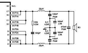
On different datasheets Tripath recommends LC combinations of 10uH/.47uF and 15uH/.22uF. Sure, apparently, used 22uH/.47uH. These give the following filter points:
10uH/.47uF = 73,412.76 Hz
15uH/.22uF = 87,611.99 Hz
22uH/.47uF = 41,148.57 Hz
I replaced the Sure 22uH coils with 10uH, but I have not yet replaced the caps. That means I’m currently running with a filter point of:
10uH/.47uF = 73,412.76 Hz
This is one of Tripath's recommended combinations. But when I replace the caps, I’ll use .33uF instead, which gives me a filter point of:
10uH/.33uF = 87,611.99 Hz
That’s the same value I’d get if I had used 15uH/.22uF.
All of these combinations work just fine. Sure may have chosen a lower frequency to filter out a little more noise, at the risk of rolling off the top end of the audio spectrum a little – a very little, less than 2dB at 20kHz for 4 ohm speakers and effectively none for 8 ohm speakers. And remember, we're talking about the tweeter here. Even if your tweeter is 4 ohms, chances are your crossover has a resister on the tweeter bringing its effective impedance near 8 ohms, maybe more.
Since I’m using a 4 ohm tweeter without a crossover (I have an active crossover), I’m pushing my filters up a little higher. But only for the psychology of it, since I can’t hear anything above 16kHz anyway.
So Col’s right: don’t get crazy over the output filters. What Sure did works just fine. I didn’t replace my coils to move my filter point, I did it to get better quality coils. Upgrading the coils gave me a chance to play with the filter frequency, but that was a fun side effect, not the reason to do it.
-dr_vega
The Tripath chips, like all switched amplifiers generate a lot of electrical switching noise, most of it above 100kHz. While this is well above the audible range, it can modulate with other frequencies to make audible distortion. Plus, it just isn’t good to send the noise along to speakers sucking up watts and heating your voice coils. So, Tripath recommends a second order filter at around 80kHz.
We’re lucky with Tripath because their switching frequency, while variable, is usually above 100kHz, which is higher than some of the other class D amps. The higher frequency means we can use a simple second order filter that is cheap and doesn’t harm the sound much.
On different datasheets Tripath recommends LC combinations of 10uH/.47uF and 15uH/.22uF. Sure, apparently, used 22uH/.47uH. These give the following filter points:
10uH/.47uF = 73,412.76 Hz
15uH/.22uF = 87,611.99 Hz
22uH/.47uF = 41,148.57 Hz
I replaced the Sure 22uH coils with 10uH, but I have not yet replaced the caps. That means I’m currently running with a filter point of:
10uH/.47uF = 73,412.76 Hz
This is one of Tripath's recommended combinations. But when I replace the caps, I’ll use .33uF instead, which gives me a filter point of:
10uH/.33uF = 87,611.99 Hz
That’s the same value I’d get if I had used 15uH/.22uF.
All of these combinations work just fine. Sure may have chosen a lower frequency to filter out a little more noise, at the risk of rolling off the top end of the audio spectrum a little – a very little, less than 2dB at 20kHz for 4 ohm speakers and effectively none for 8 ohm speakers. And remember, we're talking about the tweeter here. Even if your tweeter is 4 ohms, chances are your crossover has a resister on the tweeter bringing its effective impedance near 8 ohms, maybe more.
Since I’m using a 4 ohm tweeter without a crossover (I have an active crossover), I’m pushing my filters up a little higher. But only for the psychology of it, since I can’t hear anything above 16kHz anyway.
So Col’s right: don’t get crazy over the output filters. What Sure did works just fine. I didn’t replace my coils to move my filter point, I did it to get better quality coils. Upgrading the coils gave me a chance to play with the filter frequency, but that was a fun side effect, not the reason to do it.
-dr_vega
While we’re at it, Col’s point applies to the input filter, too. The input cap blocks DC from entering the amp and being sent to the speakers, where DC will burn up the voice coils real fast. Also, since Tripath amps put a 2.5vdc bias on the signal input, the input caps also keep that bias DC from feeding back into your pre-amp or CD player, where it might cause harm.
So we need input caps to block DC both directions. The input cap works with the input resistor to make a high pass filter. The input resistor sets the gain in combination with a couple of feedback components. Everyone seems to accept Tripath’s input resistor value, which is around 20-22kohms. With the value of the input resistor fixed, we can see what various values for the input cap give us for the input high pass filter. Tripath says it should be below 10 Hz so it doesn’t roll of the bottom end.
Tripath pretty consistently recommends 2.2uF for the input cap. Sure uses a 1uF in parallel with a .22uF for a total of 1.22uF. I think they did this to save space. The 1uF is a tiny surface mount and the .22uF is a higher quality polypro film. So lets check the filter values these produce:
2.2uF = about 3.5 Hz
1.22uF = about 6.5 Hz
.22uf = about 35 Hz
So we can see that Sure’s 1.22uF is less than 10 Hz, well “within spec” for Tripath. Even the better quality polypro cap is passing audio down to 35 Hz.
The value of the input cap isn’t critical. Anything above 1uF is going to get you below Tripath’s recommended 10Hz. I’ve personally used everything from .47uF to 10uF on Tripath amps.
Since the audio signal goes through the input caps, the quality of the cap is far more important than the value. Get really good polypro film or foil or paper-in-oil, or whatever you like, but get the best you can find.
I’m partial to “Vitamin Q type” paper-in-oil (PIO) caps and think they sound great on Tripaths (real Sprague Vitamin Qs weren’t made over .68uF, but similar ones are available in larger sizes). On my current Sure 2*100W, I’m trying Dayton polypro foils. They sound great, too.
To me, DIY is about experimenting, not building to formula. Understand what is needed and why, and then try different solutions to see how they sound. I’m as much interested in the knowledge as the amp.
-dr_vega
Re: Output stage mod
The HBR caps are high frequency bypass caps to filter the DC power supply just before it enters the chip. They filter out (mainly) any RFI AC that the board traces may have picked up.
The larger caps that Sure uses just filter down to a lower AC frequency than the Tripath spec. Since all you want is DC, filtering lower frequency AC is good, but probably unnecessary since there's unlikely to be any.
This is an example of Sure giving us something better than the Tripath spec. Changing them back to the Tripath spec actually "degrades" the amp, although it is unlikely you will hear any difference.
Another way to look at Sure's larger HBR caps is to consider them as mini-tank caps that provide a little extra power reservoir very close to the chip. A common mod on the T-amp was to provide a lot more capacitance right there, usually around 680uF. So if you want to replace your HBR caps, don't replace them with Tripath's .1uF, replace them with 680uF monsters!
I plan to add extra capacitance very close to the HBR caps, but I'm going to do it on the back of the board where there's more room.
-dr_vega
swkbkk said:
Another thing I noticed while trying to "study" the manuals is that something called "HBR"s in the Tripath manual and C29, C32, C37, C41 are having different values; 0.1uF in the Tripath and 6.8uF in the Sure manual. Can this be also related to the choice of the output caps and inductor coils?
The HBR caps are high frequency bypass caps to filter the DC power supply just before it enters the chip. They filter out (mainly) any RFI AC that the board traces may have picked up.
The larger caps that Sure uses just filter down to a lower AC frequency than the Tripath spec. Since all you want is DC, filtering lower frequency AC is good, but probably unnecessary since there's unlikely to be any.
This is an example of Sure giving us something better than the Tripath spec. Changing them back to the Tripath spec actually "degrades" the amp, although it is unlikely you will hear any difference.
Another way to look at Sure's larger HBR caps is to consider them as mini-tank caps that provide a little extra power reservoir very close to the chip. A common mod on the T-amp was to provide a lot more capacitance right there, usually around 680uF. So if you want to replace your HBR caps, don't replace them with Tripath's .1uF, replace them with 680uF monsters!
I plan to add extra capacitance very close to the HBR caps, but I'm going to do it on the back of the board where there's more room.
-dr_vega
swkbkk said:very informative and educational posts indeed, dr_vega!
Could you also kindly elaborate a bit on the role of "Differential Mode Capacitor" and on the differences between the value of 0.22uF as used in the Sure board and the value of 0.1uF?
I guess you can tell it's Friday and I don't want to do any work. Just sitting at my desk writing meandering posts about my latest toy, the 2*100W Sure. I got to say, I really like it, and, unlike some other posters, I think Sure has done a fabulous job with it. To me it seems that their choices are excellent, maximizing sound quality while keeping the cost under $50. Amazing.
That said, I can't imagine why they left out the Zobel cap. That's a protection circuit to save your TA2050 if someone trips over your speaker wire and unplugs it while your running at high power.
As to the Differential Mode cap, I don't have a clue. The Tripath docs don't say anything about it other than it exists. All of the Tripath docs show a .1uF value and Sure used .22uF. I don't know whether that is an upgrade or a downgrade, or whether Sure just had a bunch of .22uFs lying around because they didn't use them as Zobels
") .
.-dr_vega
I found this on the Differential Mode capacitor in the datasheet for the Tripath TAA4100:
"Differential Output Capacitor. Differential noise decoupling for reduction of conducted emissions. Must be located near chassis exit point for maximum effectiveness."
Not very informative to me. Also, although they include the above in the device description table, they left them off the schematic.
-dr_vega
I guess you can tell it's Friday and I don't want to do any work. Just sitting at my desk writing meandering posts about my latest toy, the 2*100W Sure. I got to say, I really like it, and, unlike some other posters, I think Sure has done a fabulous job with it. To me it seems that their choices are excellent, maximizing sound quality while keeping the cost under $50. Amazing.
Yeah, same here. I am really impressed with this little 2*100W. I had one of the old 4*100W, you can read about it here:
http://www.diyaudio.com/forums/showthread.php?threadid=111147&perpage=25&pagenumber=1
my 4*100W build:
http://minirig.org.au/2008/03/15/minirig-sure-electronics-class-d-4x100w-amp-project/
the 4*100W was an amazing little amp too but it had misgivings, mainly the noise floor was very high. I ended up replacing it with a 41hz TAA4100.
I think Sure Electronics have learned a lot since they started producing these little modules and their knowledge has culminated into the 2*100W. I particularly like the fact that you can basically look around the house pick up any old DC power supply over 12v, plug it on and it works! But not only does it work it produces excellent sound with no hiss
Hats off to Sure Electronics.
Dr Vega, have you tried the new line of Dayton Precision 1% Metallized Polypropylene Capacitors? I'm running them in my preamp and they sound great!
http://pix.minirig.org.au/main.php?g2_itemId=1162
I still have 2 left, might try them in the 2*100
col.
col said:
I think Sure Electronics have learned a lot since they started producing these little modules and their knowledge has culminated into the 2*100W. I particularly like the fact that you can basically look around the house pick up any old DC power supply over 12v, plug it on and it works! But not only does it work it produces excellent sound with no hiss
Hats off to Sure Electronics.
Dr Vega, have you tried the new line of Dayton Precision 1% Metallized Polypropylene Capacitors? I'm running them in my preamp and they sound great!
col.
Right, Col. And I think the TC2000 is a third generation Tripath chip, right? It certainly sounds more detailed than the 2030 in my Motorola DCP501, and the 2024 in my T-Amps, all of which I've modified in similar ways.
I've not tried the 1% Dayton polypro films, just the 10%, which are great. I preferred the PIO caps which are a little softer and smoother, but ultimately give up a tiny bit of detail. I'm finding the Dayton polypro foil caps are smoother than the film caps, and just as detailed. Kind of the best of both worlds. Too bad they don't come in larger values.
Right now I'm bypassing 2uF WestCap Vitamin Q types with .47uF Dayton foils - just superb.
-dr_vega
dr_vega said:These give the following filter points:
10uH/.47uF = 73,412.76 Hz
15uH/.22uF = 87,611.99 Hz
22uH/.47uF = 41,148.57 Hz
I replaced the Sure 22uH coils with 10uH, but I have not yet replaced the caps. That means I’m currently running with a filter point of:
10uH/.47uF = 73,412.76 Hz
I wrote the Sure filter wrong, although the value is correct. Sure gave us .68uF caps, so it should look like this:
22uH/.68uF = 41,148.57 Hz
And I'm currently running:
10uH/.68uF = 61,033.19 Hz
-dr_vega
I bought the 2*100W version and tried with 2 types of power supply:
1. 19.6V DC @ 4 A from Dell laptop power pack.
2. 24V DC from 4*5 Ahr battery pack connected in series and parallel to give me 24V DC (closer to 25V).
The Sure board has NO MODS at all. The latter using battery SOUNDS SO MUCH better, worth a try. On completion I will give a better assessments.
cheers.
Power Cap mod
I hope you don't mind answering another very newbie question.
Can anyone here kindly shed some light on the virtue of "power cap" modifications and on adding "tank caps"?
I observe from reading previous posts in this thread that some members here have added some extra big capacitors and/or have replaced the power caps. What are they for and what benefits can I expect from them?
And if I want to try them myself, what should I add and/or replace? Any guidelines on choosing the capacitors in terms of material, capacitance, voltage, etc?
I tried searching around but couldn't manage to find the required information.
- Status
- This old topic is closed. If you want to reopen this topic, contact a moderator using the "Report Post" button.
- Home
- Amplifiers
- Class D
- Sure Electronics New Tripath Board tc2000+tp2050