Silver Stealth said:That's right, Captn I should have clued on likewise earlier. There are no plate resistors in this design, the B+ is split equally between the tube halves via the 1M resistors.
As far as the headphone operation there are 3 main changes I can see:
1) Use R17 - value again picked from the table depending on B+ and output tube selected (100R-600R approx)
2) Short R15 and R8
3) Insert C8 over R11 (47uf-1k uf 10V)
I wonder if you and I are looking at the same users guide. I have revision C now and I found the section on headphone amps but I don't think I see all of your points.
1. I don't see an R-17 on my schematic although I do see it on the table. Where is it in the circuit? Or maybe I need a link to the latest drawing.
2. I see that R8 is shorted but it looks like R15 is still in the drawing that I have.
3. Do you mean C3 bypassing R11?
Thanks for the help. This thing is kind of a moving target. (It looks like I'd better rethink my 300 volt power supply). Hello Mouser!
Silver Stealth said:Wouldn't mind a copy of Rev C if someone would pm me I can provide email address. Thanks!
Here is a Link .
It looks like R17 has been dropped from the headphone amp although it is still listed on the table.
Thanks for that Captn
Looks like Rev C doesn't allow use of 5687 and equivs? Just as well I bought the Rev B boards then I guess....
Circuit hasn't changed fundamentally as you suggested
Still loving a quartet of 6n23p-ev from Russia (6922 exact equiv) but do have some 5687s to try in the near future...
Looks like Rev C doesn't allow use of 5687 and equivs? Just as well I bought the Rev B boards then I guess....
Circuit hasn't changed fundamentally as you suggested
Still loving a quartet of 6n23p-ev from Russia (6922 exact equiv) but do have some 5687s to try in the near future...
Brit01 said:For those using Bas's PSU V1.0 for Aikido:
How can I incorporate a simple voltage divider to the B+ output on his board?
Are you trying to reduce your B+ voltage?
Hi boywonder,
Just utilizing the psu to power a simple CF design i'm playing around with.
I've got way too much voltage as the load is very small compared to my aikido board.
Thought about tapping off a portion with a voltage divider something like the divider he uses for the 3/1 heater bias.
Maybe I can wire up the same voltage divider he defines to split the B+ by 50% with the 1M resistor to ground. Is this workable?
The 3/1 heater bias just provides a voltage reference for the heater center tap, it does not have to provide any current. Pulling any meaningful current through those large R's will burn some watts (and probably the resistors).
I would consider reducing the value of the first cap of the CRC/CLC to reduce B+. What is your present B+ and first cap value? What B+ are you shooting for?
I would consider reducing the value of the first cap of the CRC/CLC to reduce B+. What is your present B+ and first cap value? What B+ are you shooting for?

Some Pics
I thought I'd post a pic of my aikido build in progress and ask a grounding question.
First, the question. I have not yet tied the star neutral to the chassis ground. It was my plan to use a .22 uf cap and a 10R resistor in parallel so as to sink stray AC through the cap and reference the DC through the resistor. (I will use a 3 prong power cable)
What is the collective wisdom on this? I am often vexed by ground loops and I want to get this done right.
Here is a photo:
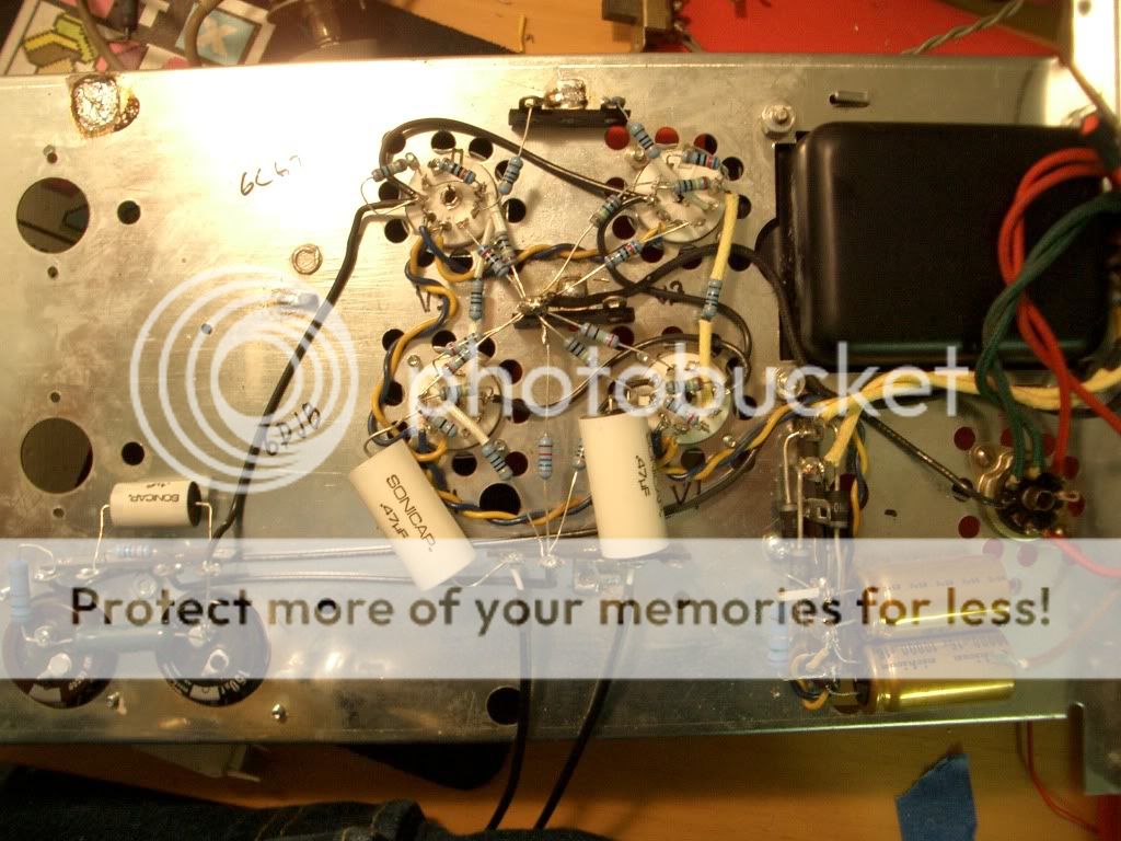
I'm using 6CG7s and 6DJ8s with EZ84 tube rectified CRC filtered 250 VDC B+. The heater voltage is DC via schotsky diodes in a bridge with 10,000 uf caps. I recycled an old yard sale Japanese 6BM8 integrated amp chassis and transformer because I so hate chassis work.
BTW- Many thanks to all here who have unknowingly helped with this build by way of your postings as well as those who have directly answered my silly questions.
-CD
I thought I'd post a pic of my aikido build in progress and ask a grounding question.
First, the question. I have not yet tied the star neutral to the chassis ground. It was my plan to use a .22 uf cap and a 10R resistor in parallel so as to sink stray AC through the cap and reference the DC through the resistor. (I will use a 3 prong power cable)
What is the collective wisdom on this? I am often vexed by ground loops and I want to get this done right.
Here is a photo:
I'm using 6CG7s and 6DJ8s with EZ84 tube rectified CRC filtered 250 VDC B+. The heater voltage is DC via schotsky diodes in a bridge with 10,000 uf caps. I recycled an old yard sale Japanese 6BM8 integrated amp chassis and transformer because I so hate chassis work.
BTW- Many thanks to all here who have unknowingly helped with this build by way of your postings as well as those who have directly answered my silly questions.
-CD
Howdy Captn
Mains earth must go to chassis - no debate here (for safety).
Star earth to mains earth often is a 10R/5W resistor with a 0.1uf MAINS RATED cap in parallel over it. The only problem with this is that in fault current situation the resistor might burn out but still leave a dangerous live chassis. Most houses have an ELCB these days so not that likely but is a potential risk for some.
You can also configure a bridge rectifier (eg 35A type) to isolate mains noise. You short the + and - together, connect this to mains earth, then connect your other grounds to the 'AC' inputs of the bridge. Nice n cheap too! ;-)
You could also combine these concepts conceivably and put the 10R/5W resistor between mains earth and the bridge. You can also try various combinations of mains rated caps of small values in parallel with the 10R/5W resistor
Try a few things and let us know what worked best for you. Cheers.
PS - good work above - makes me want to fire up the soldering iron!! Must try out those ECC182s I've got soon...
Ah yes, Rod Elliot, good practical advice and his site is full of common sense.
You can see the rectifier bridge ground loop lift in his pages, which was very similar to what I was saying with the slight twist on the resitor/cap in bypass rather than series. Safer this way too in a fault current situation.
He does ask to link to the entire site - so in doing my fellow Aussie duty here's the main page link - sound.au.com
This is the preamp I had built recently, which has tube rectified and regulated power supply. The noise cancellation capacitor had been removed.
Jim Hu
An externally hosted image should be here but it was not working when we last tested it.
An externally hosted image should be here but it was not working when we last tested it.
An externally hosted image should be here but it was not working when we last tested it.
Jim Hu
jimhu said:This is the preamp I had built recently, which has tube rectified and regulated power supply. The noise cancellation capacitor had been removed.
Jim Hu
Great work Jim!
")
Can you show us the schematic of your regulator please?
Actually the regulator comes from:
Frank's Ultimate Tube Preamp Post #74
Regulator Schematic
And two 1N4007 are replaced by 5AR4. But be careful, the filter capacitor (330uF 385V) value must be reduced for tube rectifier.
Jim Hu
Frank's Ultimate Tube Preamp Post #74
Regulator Schematic
And two 1N4007 are replaced by 5AR4. But be careful, the filter capacitor (330uF 385V) value must be reduced for tube rectifier.
Jim Hu
- Home
- Amplifiers
- Tubes / Valves
- Building a Aikido preamplifier