What are the measurement conditions of these two plots? Mic postion? Mic distance? MLS? Swept sine? RTA? Gate length? No gate? Nearest boundary?
Don't tell me I'm going through all the trouble to compare the two when one guy is using an ungated swept sine and the other a MLS signal with a 3ms gate and 1/3 octave smoothing. And being 1m for one and 2m for the other would ruin it for me too.
I did start horn testing last night though so at least we can compare these under the same measurements conditions. I'll be using the B&C DE250 for all them, but may run additional measurements with a BMS or Selenium screw on CD for that type of horn as the B&C with adaptor may unfairly penalize the screw type horns.
Mine are at 44", and Markus's, 1M, according to the record here. Pics of ZilchLab are plastered in a half-dozen forums; it's freefield, basically, but rare that I clear the room.
Tweeter height was ~53" as I recall, with a 10' - 6" ceiling height, or close to that. I adjusted the window for each measurement as the first reflection varies with mic height, and the one in the legend would be for the +30° curve, last taken but not shown. Yes, I have that plot, also, but my intent was to capture +/- 10° about the lobe center, and those curves had more like a 5 ms window, with resolution to ~200 Hz.
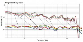
I smoothed to 1/3 octave because that's what Earl does in all of his plots and it allows visualizing the underlying trends, but I can show unsmoothed as well. I typically work at 1/6 octave, given the measurement conditions here, which are somewhat less than ideal.
Markus's plots are at 22.5° horizontal, and mine on the horizontal axis, though I posted my first look at the Geddes recommended angle earlier. As everyone now knows, Earl measures but does not publish the vertical polars for his products; this was the first independent look at the behavior, and it's clear that the system must be EQ'd at a particular vertical angle to define a desired listening window.
I doubt you intend to measure system verticals, which would require configuring a standard configuration for each horn or waveguide studied, but those are the caveats -- find the center of the vertical lobe in the particular complement and alignment (the anti-phase null gets it precisely), EQ the system there, and then measure the polars. Anything outside +/- 5° is likely to exhibit significant variability due to driver interference effects....
Tweeter height was ~53" as I recall, with a 10' - 6" ceiling height, or close to that. I adjusted the window for each measurement as the first reflection varies with mic height, and the one in the legend would be for the +30° curve, last taken but not shown. Yes, I have that plot, also, but my intent was to capture +/- 10° about the lobe center, and those curves had more like a 5 ms window, with resolution to ~200 Hz.
I smoothed to 1/3 octave because that's what Earl does in all of his plots and it allows visualizing the underlying trends, but I can show unsmoothed as well. I typically work at 1/6 octave, given the measurement conditions here, which are somewhat less than ideal.
Markus's plots are at 22.5° horizontal, and mine on the horizontal axis, though I posted my first look at the Geddes recommended angle earlier. As everyone now knows, Earl measures but does not publish the vertical polars for his products; this was the first independent look at the behavior, and it's clear that the system must be EQ'd at a particular vertical angle to define a desired listening window.
I doubt you intend to measure system verticals, which would require configuring a standard configuration for each horn or waveguide studied, but those are the caveats -- find the center of the vertical lobe in the particular complement and alignment (the anti-phase null gets it precisely), EQ the system there, and then measure the polars. Anything outside +/- 5° is likely to exhibit significant variability due to driver interference effects....
augerpro said:
I did start horn testing last night though so at least we can compare these under the same measurements conditions. I'll be using the B&C DE250 for all them, but may run additional measurements with a BMS or Selenium screw on CD for that type of horn as the B&C with adaptor may unfairly penalize the screw type horns.
Looking forward to seeing your results on the various waveguides. Thanks for taking the time to do the measurements.
I've got 4 of the large QSC waveguides sitting on my workbench just waiting for a project.
Re: The Zilch Effect:
You must be a hit at parties...
Lay the speaker on its side on a stand and you wouldn't have to change gates.
See this is where the whole thing goes off the rails. With no standard position it's easy for one set of plots to look good and another to look bad. I'm not real clear what axis Markus actually measured his Nathans? It's either on woofer, on tweeter, or the center of both, the last two of which would be reasonable as most people would set them up to have those axes at ear level. To be fair you need to pick one of those conventions, because finding the center of the lobe and then going +/- from there does not represent a typical listening axis. It's cherry picking. The main lobe could be pointed at the ceiling for all we know, but if you use it as your axis and then measure in a tight window vertically of course it's going to look better-but it's not representative of what a listener would hear in a typical installation.
That said I think it is possible that yours may be smoother through the crossover, simply because you are crossing close to the horn cutoff and my bet is that the flaring response is filling in what should be a null. You didn't intend this effect, but it is probably whats happening. After all for two non-coincident drivers using textbook slopes there MUST be a null vertically, if there is not then your response is not following any of the standard filter slopes. Where this gets hazy (to me) is what this means. This goes back to my stupid idea I posted in this thread a week or two ago. Clearly the lobing will not be predictable based off the standard filters. Could be worse or more uneven as listening position changes, which is what usually happens. But maybe not. If you have full polars and it shows the ripple to be fairly smooth, then I guess that's the proof in the pudding. Back to my idea what if you crossed right at the point the horn response flare peaks vertically? It's like a variable directivity filter that offsets the nulling effect of non-coincident drivers.
No system measurements as I have no systems to measure. I'm not measuring whole speakers, just the horns themselves. When I do build a speaker I'll do full polars, but not referenced to the main lobe as that is not accurate IMHO. I'll measure from the design axis which will probably be just below the tweeter center.
ZilchLab said:It's a nefarious intercontinental HOM conspiracy, obviously, either that, or the Mona Lisa in a grilled cheese sandwich:
You must be a hit at parties...
ZilchLab said:I adjusted the window for each measurement as the first reflection varies with mic height
Lay the speaker on its side on a stand and you wouldn't have to change gates.
ZilchLab said:my intent was to capture +/- 10° about the lobe center
See this is where the whole thing goes off the rails. With no standard position it's easy for one set of plots to look good and another to look bad. I'm not real clear what axis Markus actually measured his Nathans? It's either on woofer, on tweeter, or the center of both, the last two of which would be reasonable as most people would set them up to have those axes at ear level. To be fair you need to pick one of those conventions, because finding the center of the lobe and then going +/- from there does not represent a typical listening axis. It's cherry picking. The main lobe could be pointed at the ceiling for all we know, but if you use it as your axis and then measure in a tight window vertically of course it's going to look better-but it's not representative of what a listener would hear in a typical installation.
That said I think it is possible that yours may be smoother through the crossover, simply because you are crossing close to the horn cutoff and my bet is that the flaring response is filling in what should be a null. You didn't intend this effect, but it is probably whats happening. After all for two non-coincident drivers using textbook slopes there MUST be a null vertically, if there is not then your response is not following any of the standard filter slopes. Where this gets hazy (to me) is what this means. This goes back to my stupid idea I posted in this thread a week or two ago. Clearly the lobing will not be predictable based off the standard filters. Could be worse or more uneven as listening position changes, which is what usually happens. But maybe not. If you have full polars and it shows the ripple to be fairly smooth, then I guess that's the proof in the pudding. Back to my idea what if you crossed right at the point the horn response flare peaks vertically? It's like a variable directivity filter that offsets the nulling effect of non-coincident drivers.
ZilchLab said:I doubt you intend to measure system verticals, which would require configuring a standard configuration for each horn or waveguide studied, but those are the caveats -- find the center of the vertical lobe in the particular complement and alignment (the anti-phase null gets it precisely), EQ the system there, and then measure the polars. Anything outside +/- 5° is likely to exhibit significant variability due to driver interference effects....
No system measurements as I have no systems to measure. I'm not measuring whole speakers, just the horns themselves. When I do build a speaker I'll do full polars, but not referenced to the main lobe as that is not accurate IMHO. I'll measure from the design axis which will probably be just below the tweeter center.
Another thing about the horn flare filling in the null, if the vertical response is smoother that's a good thing, but there must be a corresponding increase in the amount of energy directed at the ceiling/floor which will end up interfering at the listener position, no? How will this impact sound? I don't knwo if this is good ro bad yet, I may have to experiment with my loudspeaker to see, unless someone can tell me why I'm completely offbase with this whole idea, which is more than a little possible!!
The ironic thing is that as you push the nulls far apart and/or fill them in you actually increase the floor/ceiling reflection energy. Which is the exact opposite of what you stated as a goal Zilch. This was the point I was trying to make weeks ago.
The ironic thing is that as you push the nulls far apart and/or fill them in you actually increase the floor/ceiling reflection energy. Which is the exact opposite of what you stated as a goal Zilch. This was the point I was trying to make weeks ago.
Re: Re: The Zilch Effect:
Yes, of course, with a rotary platform, but Earl was making a big deal of how difficult that is at 22.5° horizontal, even after we suggested some simple solutions, so Markus and I did it just by moving the mic up and down, and got useful results.
"Very hard" being the case, I have to wonder how Earl managed to obtain the 45° oblique measurements in his original study of the Econo Waveguide, topic of this thread. I believe we have smoked this one out.
It doesn't matter if the reference is the center of the forward null, which is the case in the overlaid plots. Markus's was at -10° and mine at +10°, relative to what doesn't matter, as we both show +/- 10° from there.
The point illustrated by these system vertical polar studies is that, optimally, the lobe center must be located in the region of the intended vertical listening axis, and the EQ applied there, as the response varies significantly outside a relatively narrow vertical window.
We've been focusing upon the role of the vertical nulls themselves in this discussion thus far, but we now see, subject to verification, of course, that even in the region of the lobe central axis, the influence of driver offset cannot be ignored.
Given that my curves were done with 1/3 octave smoothing, I'm not making the case you suggest, rather, that both systems exhibit strikingly similar variance about the central axis of the vertical lobe, differentially above and below the crossover frequency. We should look back to Wayne's plots to see if the effect is apparent there, as well.
That's a third theory, now, and it'll be interesting to know, ultimately, what is going on. In the meantime, since I am the first to identify the phenomenon as real, I get to say what it is, and for now, I'm going with the "Global HOM Conspiracy/Harmonic Convergence" thesis.")
It's an important distinction; we need to keep waveguide performance characteristics separate and distinct from systems. It's now clear to me from these initial studies that the location of the central axis of the vertical lobe is important in system design, as is where the system EQ is accomplished in relation to that axis.
Well, no, the objective is to get the nulls OUTSIDE the vertical pattern, substantially as Wayne advocates, and these findings further indicate the desirability of a relatively narrow vertical pattern such that the waveguide controls the floor and ceiling reflections.
Also, presumably, the wider the nulls, the flatter the forward lobe front, and the less response variability about its axis will occur....
Footnote: It's a 90° axi-symmetric PT waveguide I'm using in these verticals.
augerpro said:
Lay the speaker on its side on a stand and you wouldn't have to change gates.
Yes, of course, with a rotary platform, but Earl was making a big deal of how difficult that is at 22.5° horizontal, even after we suggested some simple solutions, so Markus and I did it just by moving the mic up and down, and got useful results.
"Very hard" being the case, I have to wonder how Earl managed to obtain the 45° oblique measurements in his original study of the Econo Waveguide, topic of this thread. I believe we have smoked this one out.
augerpro said:See this is where the whole thing goes off the rails. With no standard position it's easy for one set of plots to look good and another to look bad. I'm not real clear what axis Markus actually measured his Nathans? It's either on woofer, on tweeter, or the center of both, the last two of which would be reasonable as most people would set them up to have those axes at ear level.
It doesn't matter if the reference is the center of the forward null, which is the case in the overlaid plots. Markus's was at -10° and mine at +10°, relative to what doesn't matter, as we both show +/- 10° from there.
Originally posted by augerpro To be fair you need to pick one of those conventions, because finding the center of the lobe and then going +/- from there does not represent a typical listening axis. It's cherry picking. The main lobe could be pointed at the ceiling for all we know, but if you use it as your axis and then measure in a tight window vertically of course it's going to look better-but it's not representative of what a listener would hear in a typical installation.
The point illustrated by these system vertical polar studies is that, optimally, the lobe center must be located in the region of the intended vertical listening axis, and the EQ applied there, as the response varies significantly outside a relatively narrow vertical window.
We've been focusing upon the role of the vertical nulls themselves in this discussion thus far, but we now see, subject to verification, of course, that even in the region of the lobe central axis, the influence of driver offset cannot be ignored.
Originally posted by augerpro That said I think it is possible that yours may be smoother through the crossover, simply because you are crossing close to the horn cutoff and my bet is that the flaring response is filling in what should be a null. You didn't intend this effect, but it is probably whats happening. After all for two non-coincident drivers using textbook slopes there MUST be a null vertically, if there is not then your response is not following any of the standard filter slopes. Where this gets hazy (to me) is what this means.
Given that my curves were done with 1/3 octave smoothing, I'm not making the case you suggest, rather, that both systems exhibit strikingly similar variance about the central axis of the vertical lobe, differentially above and below the crossover frequency. We should look back to Wayne's plots to see if the effect is apparent there, as well.
Originally posted by augerpro This goes back to my stupid idea I posted in this thread a week or two ago. Clearly the lobing will not be predictable based off the standard filters. Could be worse or more uneven as listening position changes, which is what usually happens. But maybe not. If you have full polars and it shows the ripple to be fairly smooth, then I guess that's the proof in the pudding. Back to my idea what if you crossed right at the point the horn response flare peaks vertically? It's like a variable directivity filter that offsets the nulling effect of non-coincident drivers.
That's a third theory, now, and it'll be interesting to know, ultimately, what is going on. In the meantime, since I am the first to identify the phenomenon as real, I get to say what it is, and for now, I'm going with the "Global HOM Conspiracy/Harmonic Convergence" thesis.
Originally posted by augerpro No system measurements as I have no systems to measure. I'm not measuring whole speakers, just the horns themselves. When I do build a speaker I'll do full polars, but not referenced to the main lobe as that is not accurate IMHO. I'll measure from the design axis which will probably be just below the tweeter center.
It's an important distinction; we need to keep waveguide performance characteristics separate and distinct from systems. It's now clear to me from these initial studies that the location of the central axis of the vertical lobe is important in system design, as is where the system EQ is accomplished in relation to that axis.
Originally posted by augerpro The ironic thing is that as you push the nulls far apart and/or fill them in you actually increase the floor/ceiling reflection energy. Which is the exact opposite of what you stated as a goal Zilch. This was the point I was trying to make weeks ago.
Well, no, the objective is to get the nulls OUTSIDE the vertical pattern, substantially as Wayne advocates, and these findings further indicate the desirability of a relatively narrow vertical pattern such that the waveguide controls the floor and ceiling reflections.
Also, presumably, the wider the nulls, the flatter the forward lobe front, and the less response variability about its axis will occur....
Footnote: It's a 90° axi-symmetric PT waveguide I'm using in these verticals.
Re: Re: Re: The Zilch Effect:
Yes it does matter. The lobe could be anywhere, but there are only so many listening axes. I don't even know you say such a thing when you follow it with this:
Indeed.
ZilchLab said:It doesn't matter if the reference is the center of the forward null, which is the case in the overlaid plots. Markus's was at -10° and mine at +10°, relative to what doesn't matter, as we both show +/- 10° from there.
Yes it does matter. The lobe could be anywhere, but there are only so many listening axes. I don't even know you say such a thing when you follow it with this:
ZilchLab said:The point illustrated by these system vertical polar studies is that, optimally, the lobe center must be located in the region of the intended vertical listening axis, and the EQ applied there, as the response varies significantly outside a relatively narrow vertical window.
Indeed.
Re: Re: Re: Re: The Zilch Effect:
It's not "Off the rails," is what. The reference point for each of the two overlaid plots is the central axis of the vertical lobe, and thus, the results are directly comparable....
augerpro said:
Yes it does matter. The lobe could be anywhere, but there are only so many listening axes.
It's not "Off the rails," is what. The reference point for each of the two overlaid plots is the central axis of the vertical lobe, and thus, the results are directly comparable....
Re: Re: Re: The Zilch Effect:
So which is it, less or more directivity you are after here? High DI (narrow lobe) or low DI (tall lobe)? These two statements are at odds with each other. In fact the whole reduce ceiling slap by pushing the nulls apart is also at odds as they are to large extent mutually exclusive. You can't have a bigger lobe AND less ceiling/floor reflection at the same time. Also all this only matters around the crossover frequency, as above and below that the DI of the horn and woofer set the directivity, nothing you can do about it. Really I don't even know why I bother, you seem to have some cognitive dissonance where your means is actually in opposition to your end and you won't acknowledge it.
ZilchLab said:Well, no, the objective is to get the nulls OUTSIDE the vertical pattern, substantially as Wayne advocates, and these findings further indicate the desirability of a relatively narrow vertical pattern such that the waveguide controls the floor and ceiling reflections.
Also, presumably, the wider the nulls, the flatter the forward lobe front, and the less response variability about its axis will occur....
So which is it, less or more directivity you are after here? High DI (narrow lobe) or low DI (tall lobe)? These two statements are at odds with each other. In fact the whole reduce ceiling slap by pushing the nulls apart is also at odds as they are to large extent mutually exclusive. You can't have a bigger lobe AND less ceiling/floor reflection at the same time. Also all this only matters around the crossover frequency, as above and below that the DI of the horn and woofer set the directivity, nothing you can do about it. Really I don't even know why I bother, you seem to have some cognitive dissonance where your means is actually in opposition to your end and you won't acknowledge it.
Re: Re: Re: Re: Re: The Zilch Effect:
Well I'm glad it's now clear to you why the lobe axis must have some connection with listening/design axis. Because the listening axis is the correct reference for any such lobing discussion. I was starting to think all that LSD I ate as a youth was finally catching up with me. BTW Markus only mentioned the woofer center, tweeter center, and in between as teh measurement axis in his plots a few pages back. Nothing about finding the lobe maximum and measuring from there? So I'm not clear where his measurements are at, but I may very well have missed where he said it.
ZilchLab said:It doesn't matter if the reference is the center of the forward null, which is the case in the overlaid plots. Markus's was at -10° and mine at +10°, relative to what doesn't matter, as we both show +/- 10° from there.
ZilchLab said:the lobe center must be located in the region of the intended vertical listening axis
ZilchLab said:It's now clear to me from these initial studies that the location of the central axis of the vertical lobe is important in system design
Well I'm glad it's now clear to you why the lobe axis must have some connection with listening/design axis. Because the listening axis is the correct reference for any such lobing discussion. I was starting to think all that LSD I ate as a youth was finally catching up with me. BTW Markus only mentioned the woofer center, tweeter center, and in between as teh measurement axis in his plots a few pages back. Nothing about finding the lobe maximum and measuring from there? So I'm not clear where his measurements are at, but I may very well have missed where he said it.
Re: Re: Re: Re: The Zilch Effect:
It's the same difficulty Wayne was having earlier in this discussion: the lobe and nulls have nothing to do with the DI, other than introducing an anomaly in the crossover region when the nulls fall within the directivity window. As variables, they may be independently manipulated to produce a desired outcome, which, in this case, is a narrow vertical directivity established by the waveguide, with the nulls outside that window, the lobe axis coincident with the vertical listening axis, and the system EQ'd on that same axis.
augerpro said:
Really I don't even know why I bother, you seem to have some cognitive dissonance where your means is actually in opposition to your end and you won't acknowledge it.
It's the same difficulty Wayne was having earlier in this discussion: the lobe and nulls have nothing to do with the DI, other than introducing an anomaly in the crossover region when the nulls fall within the directivity window. As variables, they may be independently manipulated to produce a desired outcome, which, in this case, is a narrow vertical directivity established by the waveguide, with the nulls outside that window, the lobe axis coincident with the vertical listening axis, and the system EQ'd on that same axis.
There are a set of competing priorities that you have to balance with respect to the vertical pattern.
Larger mouths provide pattern control to a lower frequency, but wider vertical spacing increases CTC spacing, which in turn, reduces the angle of the vertical nulls.
My solution has always been to choose a horn that has narrow vertical dimension, favoring CTC spacing over pattern control in the vertical. The reason is simple: It doesn't matter what pattern control your horn has if the pattern is cut in half with interference nulls.
To me, the best balance is to use a horn that provides CD in the horizontal and has gently collapsing vertical directivity. Many of the 90°x40° horns for 1" drivers gain vertical control around 3kHz, so above that point, the horn sets the pattern. It is nice to have a relatively narrow angle to reduce ceiling slap.
This then also allows CTC spacing that supports a tall forward lobe with relatively widely spaced vertical nulls. Those sort of punctuate the pattern, defining an edge of the forward lobe where the horn alone would have a pattern that was widening up.
The horizontal pattern, of course, should be uniform so an OS or quadratic profile is nice for the side walls. The top and bottom profiles will lose directivity within the passband in a horn of these approximate dimensions, so I'm not sure that CD is needed or wanted in the vertical. When a CD horn gains directivity, it is accompanied by some ripple. The elliptical might work out, or it may be that a hybrid shape is better that gains pattern control in the vertical more gently, since it will happen within the passband.
There's been a lot of talk in the last couple of weeks, splitting hairs really, in my opinion. That's why I stayed out of the discussion for a while. I don't see any point splitting hairs on a topic that is easy to measure more on the scale of "a mile wide".
You know, if the speaker's vertical nulls are spaced so closely together that you quibble about where the forward axis should be located and/or measured, that's a pretty good indication the null angle is just plain too narrow.
We expect this from a cone/dome speaker with a high crossover point. The vertical nulls can't possibly be moved far apart in a speaker like that. But when designing speakers to provide unform coverage through a larger pattern, I think it's reasonable to pay some attention to the position and height of the forward lobe.
It isn't all that hard to design a speaker that puts the nulls out 20° or more above and below the forward axis. It also isn't all that hard to position the center of the forward lobe within 5° of the baffle normal. It just takes making it a point of focus instead of resigning yourself to "it doesn't matter to you."
If the null angle is greater than 20°, then where the center of the forward axis matters a little less to the end user. The pattern is clean over a large enough area that the listener will be in a good spot anywhere in the room as long as they're a few feet back. It might be nice to know the location of the center of the forward lobe, to orient the speakers to put that line right on the target. But with a wide enough pattern, you can be comfortable that the listeners are stitting in a good spot even without precise knowledge of the position of the forward lobe.
Only if the nulls are less than 10° does it start becoming important for the end user to know exactly where the centerline of the forward axis is. It may or may not be aligned with the baffle normal, centered on the speaker, directly between the woofer and tweeter. If the null angle is too narrow, it is entirely possible, even likely, that you're sitting in a null even if you're directly facing the woofer or tweeter.
On the other hand, for any sort of technical discussion, the exact location of the forward axis is important because it is the only reference that truly exists, at least from an acoustic standpoint. It's the line marked by equal phase between woofer and tweeter. This line is set by a complex interaction between woofer and tweeter, set by the crossover phase, electro-mechanico-acoustic phase of the drivers and horn (their rolloff contribution), the directivity of the drivers and horn and the position of the drivers on the baffle. These factors all combine to set the position and shape of the forward lobe and the vertical nulls.
If you consider the baffle normal to be an axis, you're really choosing an arbitrary value from an acoustic standpoint. It's fine to do that when showing polars on a chart, it makes a nice point of reference with an obvious visual aid. You can look at the speaker and immediately know where "straight forward" is, extend an imaginary line from the center of the speaker. But this may or may not be where the center of the forward lobe is.
Re: Re: Re: Where to get the QSC?
Well, some of augerpro's measurements are up and, so far, I don't think I wasted my 72 bucks for 8 of the 14"x10" QSC PL-000446-GP. I think there's going to be a run on them if augerpro ends up using them in the economy 2-way he's going to design with the Eminence woofer.
http://sites.google.com/site/drivervault/driver-measurements/horns-and-waveguides
catapult said:I guess augerpro's measurements will tell us. He has both the JBL and the QSC. I like the looks of the QSC. We'll see how good my 'engineering eyeball' is and whether I wasted my 72 bucks (won't be the first time).
Well, some of augerpro's measurements are up and, so far, I don't think I wasted my 72 bucks for 8 of the 14"x10" QSC PL-000446-GP. I think there's going to be a run on them if augerpro ends up using them in the economy 2-way he's going to design with the Eminence woofer.
http://sites.google.com/site/drivervault/driver-measurements/horns-and-waveguides

Brandon said he's going to do the JBL and the Pyle again with a BMS 4540 when Thomas brings one over. That said, I don't think it's going to fix everything. I think Earl's 1/3 octave curves are hiding a lot of sins that Brandon's unsmoothed curves reveal in all their glory. It's that pesky old physics thing and what happens when you have a sharp edge at the mouth and a throat that's quite a bit smaller than 1".
catapult said:Brandon said he's going to do the JBL and the Pyle again with a BMS 4540 when Thomas brings one over. That said, I don't think it's going to fix everything. I think Earl's 1/3 octave curves are hiding a lot of sins that Brandon's unsmoothed curves reveal in all their glory. It's that pesky old physics thing and what happens when you have a sharp edge at the mouth and a throat that's quite a bit smaller than 1".
Given a choice of a waveguide that measures smoothly and a waveguide that has superior directivity, I'll take the latter. Frequency response can be EQ'd, directivity cannot.
This whole debate was argued to death when LeCleach was posting about the smooth frequency response of his horns.
Patrick Bateman said:Given a choice of a waveguide that measures smoothly and a waveguide that has superior directivity, I'll take the latter. Frequency response can be EQ'd, directivity cannot.
This whole debate was argued to death when LeCleach was posting about the smooth frequency response of his horns.
EQ isn't going to fix that high-Q null at 11K in the Pyle Econowave. Hopefully it will do better with a proper screw-in driver. And I'm sure some minor throat surgery could help it as well.

- Status
- This old topic is closed. If you want to reopen this topic, contact a moderator using the "Report Post" button.
- Home
- Loudspeakers
- Multi-Way
- Horn vs. Waveguide