blindsjc said:Hi friends,
Any comments about the
project of power and output
transformers that I uploaded?
Hi Blindsjc
It seems to me you are in the ballpark but I can't find the stack height of the core you plan to use.
Looking at choosen induction (more or less 1 Tesla) I suppose your iron is of "standard" grade.
If you can obtain M6X grade lams, you can rise induction up to 1.3 tesla for the power project at no risk.
This will reduce turns number, freeing space for larger wire meaning less copper losses and better regulation.
Applying the same methode to the output project will have similar effects, plus an improvement in hi frequency range because the leakage inductance decreases as the square of the primary turns number.
As the published photos imply, I'm not a professional winder and have no experience on building guitar amps where goals are clearly different than in an HI FI amp.
If I correctly understand the remarks from Bud, you may observe the number displayed for permeability (the "µ approx" field at bottom left ) while playing with the "Freq" and "Watts" parameters (upper left) after having locked the current turns number by clicking once on the "Turns per Volt" label at top left of the "copper" window".
It becomes red to remaind you.
Click again to go back to normal mode.
The peak in permeability is usually around 0.8 Tesla.
BudP,
So your French is as poor as my English

Thanks for the linked paper.
Yves.
Hi Yves,
The core tongue haves aprox. 28x38 and is
37mm tall. The laminations are GO.
I will consider the "you are in the ballpark"
like something good, because I don't know
the real mean ok. haha. But I think that this
project can work, so I need to work to improve
the performance. Is this the real mean?
Bud
I'm back to RH to try understand the comments
about permeability, I think I need some more
theory load to understand it.
Just to comment about, how Internet and
this forum is great, people from Brazil, USA
and France exchanging a lot of info. Amazing.
Thanks friends
Blindsjc
blindsjc said:Hi Yves,
The core tongue haves aprox. 28x38 and is
37mm tall. The laminations are GO.
I will consider the "you are in the ballpark"
like something good, because I don't know
the real mean ok. haha. But I think that this
project can work, so I need to work to improve
the performance. Is this the real mean?
Yes, good !
But since you have GO lams, consider increasing induction as suggested in the previous post.
Sure, it will work
Yves.
You're welcome !resident said:Yves, your winding machine is really great!
Does the meter count backwards too?
The meter was bought as is, and, no it can't count backward.
It receives pulses from the Hall effect sensor.
When I need to roll "backward" I flip the bobin

Can't tell, I copied this files from another site, Paint Shop Pro can open'em.
I have downloaded your files but I didn't find any schem for the meter. Also I can't open the .png files. What program is this?
Yves.
Yves,
No, my French is only good enough to look at the pictures in PHOTO magazine with, and dream of cold potato soup, made correctly.
You are correct that M6 will be better for efficiency and heat. There are however some problems with guitar amplifiers, as compared to audio reproduction amplifiers.
These amplifiers are much more sensitive to changes that affect the leading edge of transients, which is almost all of the music played with electric guitar. This sensitivity is what is utilized by the "Tone Meister's" who regularly "mod" amps to more closely suit customers in their player-centric taste.
Using M6 core in a power or a choke will affect the overall response lag time that players learn to work with, as part of their musical experience. Not that M6 is bad, just that in most cases it is too "fast" for the power supply needs of guitar amps. Just fine for Audio reproduction amps though. Actually much better to go for brute force and less expensive core here, just for the guitar amps.
In the OPT the same holds true. Back in the day of Peerles, UTC, Partridge, Drake and Dagnell, the core of choice for guitar amps was M19, with a more bass oriented material in M27. Again this is transient related, as the M27 allows the antenna event to form, in the core window, more slowly from 250 Hz up than M19 will. This means there is a greater phase lead, for low frequencies, from M27 and so it sounds as if the amp has more bass. Plus the overall transient character is a little slower, which allows the brain to recognize more information, from this already very fast amplifier, feeding very efficient and not at all flat in frequency response Vs amplitude speakers.
All of our power transformers use M50 or M19 core and the same is true of the OPT/s and chokes. We can do this because of how we actually stack the core. We have found a way to effectively eliminate reminence, so no zero crossing distortion, phase lagged, back half of the signal wave form troubles our devices.
We use the dielectric circuit formed with materials with different dielectric constants and specific forms of decoupling in the winding order, of primary and secondary, to obtain the "voices" I note on that sheet. Mostly an engineering solution and very repeatable, but I always have musicians choose just which set of materials Vs core Vs winding order is suitable for making music.
I will publish these designs and a picture book construction guide, before I pass from this realm... I hope.
Bud
This is very interesting Bud!BudP said:....Plus the overall transient character is a little slower, which allows the brain to recognize more information.....
Yves, I have visited this site but I can't find info about the materials.Yvesm said:
If they are M6 , M19, M50 ...... The only thing I can understand is that the first laminations are 0.50mm thick & the second one 0.35mm.
blindsjc,
For Fender or Marshal
1/2 Pa
S
S
Pb
S
S
1/2 Pa
For modern high gain
Pa
S
S
Pb
S
S
Pa
S
S
Pb, this winding should be one imperial wire size bigger than other 3
primary sections, to balance DCR within 1 ohm. Pa and Pa are paralleled as are Pb and Pb, all secondaries are in series.
There are other interleaves you can use. All will affect the way the amp responds, just as will differing dielectric materials. Matching the "permitivity" of the dielectrics to that of the core is the heart of "voicing" the OPT. Then choosing the interleave, P/S, controls the "feel" of the amp, with the Fender/Marshall interleaving being very familiar in response.
The second set of interleaves is also ideal for Audio Reproduction amps.
Bud
BudP said:The most common guitar amp winding style is as follow. If you consider the primary as two halves of the total winding, part A and part B. Then you should wind 1/2 of the primary part A turns first, using a layer of paper at least 1.75mm wider than the winding width for each layer. This means that the winding width must be 3.5mm narrower than the length of the center tongue of the E.
Then put two wraps of a high voltage dielectric plastic (Nomex 410 0.075mm thick minimumX2 layers) over the 1/2 of primary winding A. Then wind the 4 ohm secondary, probably best to split the wire size and make two windings of it here. Then two more wraps of the dielectric plastic.
Then wind all of the B winding, again using the layer paper. When done wind two layers of dielectric plastic.
Then wind the remaining turns needed for the 8 ohm and 16 ohm winding, using correct wire sizes for both load currents.
Then two more wraps of dielectric plastic.
Then the final 1/2 of the primary A winding, again using the layer papers. Then a final two layer wrap of the dielectric paper.
EDIT: oups! Sorry Bud but we posted at the same time! Anyway here is what you said above with the details..
Bud,
I'm a little bit confused with the secondaries. They are in parallel or separate windings?
I mean you must wind a secondary with two wires at the same time? Or just wind the first S and then the other one? And connect them in parallel?
General question:
Is there any simple method to measure the frequency responce of an OPT? I mean without placing it in a circuit.
I think you can't just connect a signal generator at the primary and measure the responce with an oscilloscope at the secondary....
resident,
Sorry I was not clear on secondary windings.
I am always attempting to wind any coupled winding in a single layer. If possible, then, I will wind four 4 ohm windings, in single layers and parallel them for the 4 ohm tap. Then I will attempt to wind the series extension to 8 ohms with a bifillar or even triffilar single layer winding also paralleled. Finally the further series extension to 16 ohms. Again I attempt to wind this as a single layer.
This is based upon the Fender/Marshall winding order:
1/2 Pa
4 ohm
4 ohm
Pb
8 ohm series extension
16 ohm series extension
1/2 Pa
One or more of these secondary windings will end up using more than 1 layer. With this winding organization that is ok. The loss in coupling Vs capacitive and leakage inductance losses is nicely balanced in this winding layout and an additional layer or two or three will not have much impact.
This is based upon the Hi Def winding order:
Pa
4 ohm
4 ohm
Pb
4 ohm
4 ohm
Pa
8 ohm series extension
16 ohm series extension
Pb next bigger diameter of wire from Pa is used here.
This winding layout is much more demanding of single layer secondary winding sections. You can have one extra layer without a great difference in performance, but more than that creates problems. Typical of higher Q in anything really.
So, a mix of parallel and series connections in both primary and secondary. This sort of arrangement is followed in all of my designs. And yes, I do deliberately distort these various organizations to help produce the inherent "voices" But, that and the rest of the needed information to do so yourself will cost you a lot of time or a lot of money to acquire. But, the basic building blocks are here in this thread.
Obviously you cannot always wind to suit best coupling. If you are involved in a cut throat. business shoot out, where size and cost are of paramount importance, then concerns with maximum transform of non linear signal is thrown out the window.
I do not actually measure frequency response for guitar OPT's. I am sure it is of objective interest, as a point of information, but it has no application in this particular field. You cannot "design" to a particular frequency response and automatically have a corresponding usefulness as part of a musical instrument. In actuality, having them played by a master of stringed instruments, will be of more use.
Of course, if you just wind a primary and then a secondary and call it good, your capacitive losses plus leakage inductances losses Vs your coupling area, are going to provide a transformer that just barely can get to 9 kHz, about -6 dB would be typical. Plus your THD, IM distortion and phase shift will be horrendous. But, you will have a very nice hump in the midrange and if the amplifier is tailored to this OPT, a musical, if somewhat limited range of expression, will be available.
If there is an "art form" to transformer mfg. this is it. You must still pay attention to basic safety considerations and thermal considerations, all of our power and OPT's are built to CE 6500 design criteria, but "playing" with most other first order approximation formulas and theories, for transformer design, is required.
Bud
Thanks Bud for all of the information!
I'm thinking seriously to transform that sewing machine into a winding transformer machine
The motor works great and it has a pedal to control the speed!
I need to find some small wheels and a meter to complete it!
My plans is a small wheel after the motor and a bigger one after that. So "action" won't be so hard! Like it'll be directly from the motor....
I'll try that Fender/Marshall winding order maybe for a Bassman or Showman clone! It'll be great if I can wind it and have a good result!
An OPT for a guitar amp doesn't need to go as low as one in hifi use.
The lowest freq is about 70Hz. Please correct me if I'm wrong.
By the way, how much is for a bass? Just for curiosity....
resident,
I design for flat (-.5 dB) at 60 Hz. This puts me at -3 dB at 40 Hz which gives plenty of low end power. This is the portion of the signal realm controlled by reactive impedance matching.
This is the addition in parallel of Rl and Rp and then adding the primary DCR in series to that sum. Then divide by 2 pi and the frequency you are interested in and this gives you the amount of inductance you need for - 3dB at that frequency of interest.
Core material has a hump to it's permeability and inductance is tied to this hump. Utilizing this hump to obtain the required inductance Vs frequency Vs power is part of what you must learn. Too much inductance is as bad as too little, but the sweet spot is fairly broad. We can cover this later. For now, use Yves calculator, as it is quite good and will teach you the correct range to be in, for best performance.
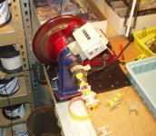
Your plan for a small pulley to large is a good one. Use as thin and flexible a belt as you can find. Here is a picture of our hand guided style of winding machine. The stand is a cast iron plain bearing pillar. The main shaft is tapered for the three jaw chuck. The large flywheel is made from phenolic, is very smooth and has a hand grip edge, out side of the pulley. We have them made at a local machine shop for $50 each,
Having the hand grip available and smooth will improve your winding ability enormously. Do not be tempted to use wood here as it is just too abrasive. Also, note the woven white fiberglass tape loops on the table edge and the same white tape background up on the table. All are important and the coil wire is fed up through the loops and then through the winders fingers for control. The motor is an 1/8th horse AC/DC brush style motor.
Bud
I design for flat (-.5 dB) at 60 Hz. This puts me at -3 dB at 40 Hz which gives plenty of low end power. This is the portion of the signal realm controlled by reactive impedance matching.
This is the addition in parallel of Rl and Rp and then adding the primary DCR in series to that sum. Then divide by 2 pi and the frequency you are interested in and this gives you the amount of inductance you need for - 3dB at that frequency of interest.
Core material has a hump to it's permeability and inductance is tied to this hump. Utilizing this hump to obtain the required inductance Vs frequency Vs power is part of what you must learn. Too much inductance is as bad as too little, but the sweet spot is fairly broad. We can cover this later. For now, use Yves calculator, as it is quite good and will teach you the correct range to be in, for best performance.
Your plan for a small pulley to large is a good one. Use as thin and flexible a belt as you can find. Here is a picture of our hand guided style of winding machine. The stand is a cast iron plain bearing pillar. The main shaft is tapered for the three jaw chuck. The large flywheel is made from phenolic, is very smooth and has a hand grip edge, out side of the pulley. We have them made at a local machine shop for $50 each,
Having the hand grip available and smooth will improve your winding ability enormously. Do not be tempted to use wood here as it is just too abrasive. Also, note the woven white fiberglass tape loops on the table edge and the same white tape background up on the table. All are important and the coil wire is fed up through the loops and then through the winders fingers for control. The motor is an 1/8th horse AC/DC brush style motor.
Bud
Attachments
- Status
- This old topic is closed. If you want to reopen this topic, contact a moderator using the "Report Post" button.
- Home
- Amplifiers
- Tubes / Valves
- OPT Design Assistante (EL84)