

Surprisingly Good Performance - The Amplifier of 100 Transistors
I finally got around to rolling out the distortion test set and the Amplifier of 100 Transistors to measure its performance.
I would like to say that I don't care - and that the whole thing is an engineering abortion. A complicated joke, and that the measurements don''t matter. The fact that I am making the measurement would however show me to be a liar - as if I didn't care, then why did I do this?
Anyway, with low distortion measurements, getting your head around the baseline of your test gear is key. With all gains / levels being equal, here is the loop-back distortion of the test system:
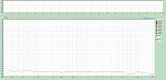
Which is fine, rolls along at about 0.0003% across the band.
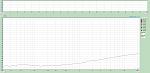
Then I ran a sweep of the Amplifier of 100 Transistors with NO load at 3dB below clipping:

OK, this is saying the amplifier distortion raises it's head above the noise floor at 1KHz and is 0.0006% at 2KHz, rising to 0.0025% at 10KHz.
Probably not the best implementation of this amplifier topology (blameless) but given the gross layout issues getting power and drive to the multitude of microscopic output devices, I am frankly surprised.
Additionally, the VAS has a bog standard miller cap, which I have done nothing whatsoever to tweak. Oh, and because every device is a BC549/559 (or 54/558 in the case of the output devices) the VAS amplifier is - well - a BC548. Probably not bad, as the 548 has 2-3pF Cbc, and is quite fast. But not optimised.
Hey, all is looking surprisingly good. So lets throw a load on and measure. I have a small collection of dummy loads, ranging from 25W aluminium cased heat-sunk units through to monster nichrome coils. Of course I grabbed the largest.
And made the following mortifying measurements: AAAaaaaarrrrggghh!!!

and WORSE on 4R!

Woe and betide, this is not what I wanted to see! How could a dearly beloved BC549 do this to me?
Initially I concluded that I had completely buggered something up, then I cogitated on the thought that the BC549 gods had taken offence to my mistreatment of such a stalwart of the small signal domain.
So I moved the measurement point to the feedback point in the amp and repeated WITH THE SAME LOADS. The distortion disappeared!!!
Coils don't introduce distortion, well not air core copper wire!
WTF? I was betting the output coil was inducing asymmetric currents into the base drive of the output stage, or that the drive was saturating... Can't be if there is more or less NO distortion at the feedback point.
I then looked at the layout and position of the coil relative to power traces. Was there induction INTO the output coil? Moved that and the problem remained.
Drinking coffee and thinking, logic prevailed. If the only thing that causes the distortion is connecting the dummy load, then... it is the dummy load itself. Clearly the Nichrome wire or the connections are either vibrating, or dodgy in some way!
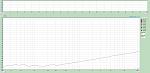
Using a REAL dummy load - here is what the Amplifier of 100 Transistors does into 8R:
And 6R:
And 3R:

Looking at the 8R curves, as these are probably a fair assessment fof the Amplifier of 100 Transistors, considering the size and SOAR of the output devices...
Freq No load 8R
200 0.0003% 0.0003% (noise floor)
500 0.0003% 0.0003% (noise floor)
1000 0.0003% 0.0006%
2000 0.0006% 0.001%
5000 0.0015% 0.0025%
10000 0.0025% 0.0044%
Which I think is quite blameless. In fact I think this is pretty good given the absence of iterative tuning.
I do believe the high frequency end could be improved through tweaks the VAS, and that the power layout is responsible for no small part of the high end distortion. But nevertheless, I think that for a fistfull of BC549 devices, this is a little cracker of an amplifier.
It makes me smile.
I am positive it will sound wonderful - but then, any 10-15W amplifier comprised of BC549's will NECESSARILY sound great, wont it?
Why would it NECESSARILY be good?... Because as I started with the dogmatic statement that: "Ïf you can't do it with a BC549, then it isn't worth doing!"
If you want a go at one of these, let me know - I will provide the CAD files. Maybe you can tweak it to improve that last octave of distortion...
I would like to say that I don't care - and that the whole thing is an engineering abortion. A complicated joke, and that the measurements don''t matter. The fact that I am making the measurement would however show me to be a liar - as if I didn't care, then why did I do this?
Anyway, with low distortion measurements, getting your head around the baseline of your test gear is key. With all gains / levels being equal, here is the loop-back distortion of the test system:

Which is fine, rolls along at about 0.0003% across the band.
Then I ran a sweep of the Amplifier of 100 Transistors with NO load at 3dB below clipping:

OK, this is saying the amplifier distortion raises it's head above the noise floor at 1KHz and is 0.0006% at 2KHz, rising to 0.0025% at 10KHz.
Probably not the best implementation of this amplifier topology (blameless) but given the gross layout issues getting power and drive to the multitude of microscopic output devices, I am frankly surprised.
Additionally, the VAS has a bog standard miller cap, which I have done nothing whatsoever to tweak. Oh, and because every device is a BC549/559 (or 54/558 in the case of the output devices) the VAS amplifier is - well - a BC548. Probably not bad, as the 548 has 2-3pF Cbc, and is quite fast. But not optimised.
Hey, all is looking surprisingly good. So lets throw a load on and measure. I have a small collection of dummy loads, ranging from 25W aluminium cased heat-sunk units through to monster nichrome coils. Of course I grabbed the largest.
And made the following mortifying measurements: AAAaaaaarrrrggghh!!!

and WORSE on 4R!

Woe and betide, this is not what I wanted to see! How could a dearly beloved BC549 do this to me?
Initially I concluded that I had completely buggered something up, then I cogitated on the thought that the BC549 gods had taken offence to my mistreatment of such a stalwart of the small signal domain.
So I moved the measurement point to the feedback point in the amp and repeated WITH THE SAME LOADS. The distortion disappeared!!!
Coils don't introduce distortion, well not air core copper wire!
WTF? I was betting the output coil was inducing asymmetric currents into the base drive of the output stage, or that the drive was saturating... Can't be if there is more or less NO distortion at the feedback point.
I then looked at the layout and position of the coil relative to power traces. Was there induction INTO the output coil? Moved that and the problem remained.
Drinking coffee and thinking, logic prevailed. If the only thing that causes the distortion is connecting the dummy load, then... it is the dummy load itself. Clearly the Nichrome wire or the connections are either vibrating, or dodgy in some way!
Using a REAL dummy load - here is what the Amplifier of 100 Transistors does into 8R:

And 6R:

And 3R:

Looking at the 8R curves, as these are probably a fair assessment fof the Amplifier of 100 Transistors, considering the size and SOAR of the output devices...
Freq No load 8R
200 0.0003% 0.0003% (noise floor)
500 0.0003% 0.0003% (noise floor)
1000 0.0003% 0.0006%
2000 0.0006% 0.001%
5000 0.0015% 0.0025%
10000 0.0025% 0.0044%
Which I think is quite blameless. In fact I think this is pretty good given the absence of iterative tuning.
I do believe the high frequency end could be improved through tweaks the VAS, and that the power layout is responsible for no small part of the high end distortion. But nevertheless, I think that for a fistfull of BC549 devices, this is a little cracker of an amplifier.
It makes me smile.
I am positive it will sound wonderful - but then, any 10-15W amplifier comprised of BC549's will NECESSARILY sound great, wont it?
Why would it NECESSARILY be good?... Because as I started with the dogmatic statement that: "Ïf you can't do it with a BC549, then it isn't worth doing!"
If you want a go at one of these, let me know - I will provide the CAD files. Maybe you can tweak it to improve that last octave of distortion...
Total Comments 2
Comments
-
 Nice..deserves a thread on the solid state forum ...Posted 5th June 2016 at 02:36 PM by kasey197

-
Have you put any thought about PSRR? IMO youll have a more enjoyable outcome by designing an AMP with xtreme PSRR measurements than vanishing low THD measurements. I see all too often over emphasis on designing an amp with super low THD measurements, but end up with a dry, brittle, sterile amp. But the opposite it true for those who focus on PSRR as there main objective. Just my 2 cents, since I really like your amp build.Posted 10th June 2016 at 05:47 AM by erik777
Updated 10th June 2016 at 05:54 AM by erik777

