Well Ive managed to finish these speakers, after a long absence from working on them, getting tied up with other projects (also unfinished), and the birth or my son in May.
The original design threads are here:
http://www.diyaudio.com/forums/multi-way/157156-taper-ratio-tl.html
http://www.diyaudio.com/forums/multi-way/158116-my-visaton-tqw-tube-speaker-eventually-started.html
I intend to Post my construction pictures here, since they are likely deleted long ago, from the original threads. I can re-post Boxim plots and crossover schematics , box dimensions etc, if anyone is interested.


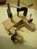


Originally, I intended on using a triangular prism shape, as shown in one of the two sketch-up pictures.
In the end I gave up hope of getting the CNC man to cut my 105° angles, and route grooves which were essential to the prism design. So I ended up making a conventional looking box. Slightly disappointing, but nevertheless essentially the same design.
Ive probably got all the CAD panel drawing somewhere, although id have to scan them.
The original design threads are here:
http://www.diyaudio.com/forums/multi-way/157156-taper-ratio-tl.html
http://www.diyaudio.com/forums/multi-way/158116-my-visaton-tqw-tube-speaker-eventually-started.html
I intend to Post my construction pictures here, since they are likely deleted long ago, from the original threads. I can re-post Boxim plots and crossover schematics , box dimensions etc, if anyone is interested.
Originally, I intended on using a triangular prism shape, as shown in one of the two sketch-up pictures.
In the end I gave up hope of getting the CNC man to cut my 105° angles, and route grooves which were essential to the prism design. So I ended up making a conventional looking box. Slightly disappointing, but nevertheless essentially the same design.
Ive probably got all the CAD panel drawing somewhere, although id have to scan them.
Last edited:
The beginning...
In the beginning I was inspired by the Vib130TL kit/project on the Visaton site:
Visaton - Lautsprecher und Zubehör, Loudspeakers and Accessories
In many ways this enclosure still appeals. The damped impedance, and almost aperiodic operation, and nice ~6dB bass roll off being the high points. I may still build this cab, just to compare with my design, which ended up being tuned using the MJK worksheets, and excel calculator; and copious help from others.
Much help and mathcad sims from Pkitt, who never seems shy to assist others.
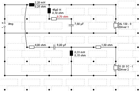
The crossover is essentially identical to the Vib130tl:
http://www.visaton.com/bilder/weichen/gross/vib130tl_w.gif
and mine, never uploaded. just realised.
Anyway, I began by adding a 45uH coil in the shunt circuit of the woofer, and used 5.5uF, the 2.2mH stayed the same. After a bit of a re-design, and from re-simming to re-obtain screenshots, of the ACTUAL size of cabinet.....
The original design employed a 2cm roundover, but I havent found a good way to do this yet. I more of a hack n slash carpenter, than a real woodworker
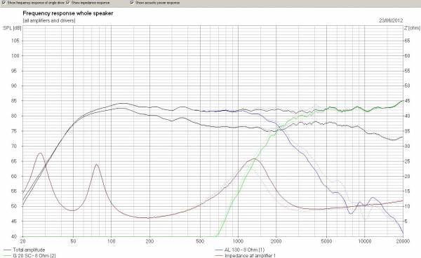
Comparing my simulation with the Measurements of the VIB130TL on the Visaton site; my design is quite favourable.
http://www.visaton.com/bilder/frequenz/gross/vib130tl_fs.gif
Suffice it to say, Im quite happy at the result in simulation of the final implementation. It does indeed sound as flat as it looks. You can hear the swell in the lower range of the g20sc, but it isnt awful. Considering the few components it does rather well.
Besides I have alternative plans for the Fountek Neo3.5H ribbon, if I feel like a change and fancy tackling 4th order stuff on Boxsim.


AT the moment though, Im quite happy. I literally have a 12" square piece of fairly dense PU foam 1" thick curled up at the rear of the woofer end of the cabinet.
In the beginning I was inspired by the Vib130TL kit/project on the Visaton site:
Visaton - Lautsprecher und Zubehör, Loudspeakers and Accessories
In many ways this enclosure still appeals. The damped impedance, and almost aperiodic operation, and nice ~6dB bass roll off being the high points. I may still build this cab, just to compare with my design, which ended up being tuned using the MJK worksheets, and excel calculator; and copious help from others.
Much help and mathcad sims from Pkitt, who never seems shy to assist others.
The crossover is essentially identical to the Vib130tl:
http://www.visaton.com/bilder/weichen/gross/vib130tl_w.gif
and mine, never uploaded. just realised.
Anyway, I began by adding a 45uH coil in the shunt circuit of the woofer, and used 5.5uF, the 2.2mH stayed the same. After a bit of a re-design, and from re-simming to re-obtain screenshots, of the ACTUAL size of cabinet.....
The original design employed a 2cm roundover, but I havent found a good way to do this yet. I more of a hack n slash carpenter, than a real woodworker
Comparing my simulation with the Measurements of the VIB130TL on the Visaton site; my design is quite favourable.
http://www.visaton.com/bilder/frequenz/gross/vib130tl_fs.gif
Suffice it to say, Im quite happy at the result in simulation of the final implementation. It does indeed sound as flat as it looks. You can hear the swell in the lower range of the g20sc, but it isnt awful. Considering the few components it does rather well.
Besides I have alternative plans for the Fountek Neo3.5H ribbon, if I feel like a change and fancy tackling 4th order stuff on Boxsim.
AT the moment though, Im quite happy. I literally have a 12" square piece of fairly dense PU foam 1" thick curled up at the rear of the woofer end of the cabinet.
Last edited:
SO hows the sound?
Well, not bad.
I sense a little low midrange mush, but since Ive not used any polyfibre fill at the moment, OR felt lining on the walls, I expect alot of that should disappear once I sort the lining and complete the tuning procedure.
The TL vent holes, arent entirely optimal. They are both 38mm diameter, and I feel the tuning is a little too high. Using a spade type bit, in my unskilled hands, chipping of the ply veneer top surface was, I guess, inevitable.
I am considering trying to find some port tubes with a panel cut out of 38mm, and a flanged outer edge, and cut to the panel thickness, to use a port 'inserts' and neaten the appearance. In this way it would be possible to reduce the vent area, slightly, and lower the tuning again.
Having said that, polyfill may be enough. The resonant effects are only slight, and im surprised that its not worse.
I attribute this a little to the intended 20:1 taper ratio. This in actuality is more like 442cm² : 22.7cm² or 19:1 and the line is 99 cm long, excluding vent shortening, if applicable.
Without a doubt, playing with stuffing will improve the lower mids, but they arent all that bad anyway, and the vent output is Gooooood
A good project, mondo. That metal AL130 woofer is quite a difficult driver to align on phase isn't it? Didn't really enjoy tangling with it in Boxsim, TBH.
You've done a very nice job on the cone breakup with that RCL woofer filter. That was a new one to me.
I noticed that 4.7uF on the soft dome tweeter was a bit kinder to it on suppressing the 1.7kHz Fs resonance than 6uF and improved phase matching from 2-5kHz with a tiny dip in frequency response. You are after all, taking it lower at crossover point than it would normally like. I wonder what effect a tweeter Zobel would have too? Say 6.8R and 0.68uF? Always like them. Smooth.
FWIW, I also suspect you could have rounded and optimised a lot of those values to preferred values and saved yourself some piggybacking of components. Enjoyed reading about it very much. Thank you for sharing.
spot on, the 6uF aligns phase better, 5uF isnt bad FWIW. I have 6x1uF piggybacked anyway, so a simple operation to change for listening tests.
However 6uF appears to protect the tweeter well enough, at the moment.i dont consider a zobel necessary since the G20SC has a rather good impedance plot anyway.
The fountek tweeter version, i have simmed a zobel of 20 ohm and 18 uf works well, neither tweeter has much of a resonant impedance peak though, so its an after thought, which could be added to the front end, perhaps on the reverse of the terminal plate.
If i should find it necessary lol.
Last edited:
or was it the other way round? 5uF gives a small improvement in phase, and slightly better tweeter protection, the 6uF flatter response and better phase slightly lower down the plot. If i recall correctly. I pondered this along while ago and decided i could just snip one of the caps out, if need be. So i may end up settling for 5uF. The tweeter impedance is rather flat though, so if anything i may add a zobel to the woofer circuit, the g20sc doesnt need one, unless im sorely mistaken.
After a heavy and varied listening session, I have reached the conclusion that 5uF is the final value. I could easily live with the 6uF, but id rather safeguard the tweeter a little more.
I have plenty 0.5uF here so i couldve met in the middle, at 5.5uF, but dont really see the need at this point.
Adding a zobel may be worthwhile in the long run, but im happy with the sound, and the impedance plot isnt bad really, and i like the simplicity of the filter as is.
I have plenty 0.5uF here so i couldve met in the middle, at 5.5uF, but dont really see the need at this point.
Adding a zobel may be worthwhile in the long run, but im happy with the sound, and the impedance plot isnt bad really, and i like the simplicity of the filter as is.
Last edited:
During yesterdays long listening session, I was frankly rather happy.Bass is slightly full, due to the temporary tuning, but not boomy.
I am somewhat shocked at the amplitude of the sub fs bass, a very weighty quality i hadnt expected.
Of course this is due to the room and speaker combo, rather than the speaker alone.
In 'Hitchhikers Guide' the rumble when Marvin fires the point of view gun at the Vogon is; really rather spectacular.
Im a very happy audiofool.
'So long and thanks for all the fish' also lived up to the brilliant recording.
Next up, 2001: A Space Odyssey
Full design and construction to be added to my freewebs site when time allows, inc measurements, when i get the equipment.
In DIYA tradition, anyone that wishes are free to try this design for themselves.
Next up, 2001: A Space Odyssey
Full design and construction to be added to my freewebs site when time allows, inc measurements, when i get the equipment.
In DIYA tradition, anyone that wishes are free to try this design for themselves.
Last edited:
Hello! I hope someone sees this post because the original thread is from several years ago.
I have been thinking about building a speaker with AL130 and G20SC too. For my first one I used W170S-4 and SC10N and I think the AL130+G20SC combo would be a step up in sound quality.
Also the Boxsim program had an update recently (Dec 2018) with new driver files and in my experience it does simulate the frequency range a little differently.
I made my crossover for the drivers and I am asking an opinion from more experienced DIYers than myself.
Crossover point is 3000hz which I think is better for this tweeter than 2000hz because of its resonant frequency of 1900hz. Phase seems to align well enough and the woofer's diffraction point of around 5000hz is at -15db. I have learned that aluminum woofers are more prone to their diffraction being audible and that may be quite nasty sound. So is -15db enough? Simulated cabinet is vented 10 litres with tuning frequency of 45hz.
Thanks for anyone who shares their thoughts on this!
I have been thinking about building a speaker with AL130 and G20SC too. For my first one I used W170S-4 and SC10N and I think the AL130+G20SC combo would be a step up in sound quality.
Also the Boxsim program had an update recently (Dec 2018) with new driver files and in my experience it does simulate the frequency range a little differently.
I made my crossover for the drivers and I am asking an opinion from more experienced DIYers than myself.
Crossover point is 3000hz which I think is better for this tweeter than 2000hz because of its resonant frequency of 1900hz. Phase seems to align well enough and the woofer's diffraction point of around 5000hz is at -15db. I have learned that aluminum woofers are more prone to their diffraction being audible and that may be quite nasty sound. So is -15db enough? Simulated cabinet is vented 10 litres with tuning frequency of 45hz.
An externally hosted image should be here but it was not working when we last tested it.
An externally hosted image should be here but it was not working when we last tested it.
An externally hosted image should be here but it was not working when we last tested it.
Thanks for anyone who shares their thoughts on this!

Another way to do it.
To link to Dropbox content.
SHARE the Dropbox image and copy the supplied hyperlink.
When pasting the hyperlink into a forum page or even on the browser address bar.... Change e.g. "www.dropbox.~" to "dl.dropboxusercontent.~"
Allows linking to images rather than Dropbox shared image page.


Wow old
Hi,
This was my project where I actually bought decent drivers!
If memory serves the XO point on the design was somewhat higher than 2k... without a dip (though that may not be an issue anyway) and achieved 8-10dB attenuation at the tweeter Fs (1900 Hz)
Is it enough attenuation?
Probably not.
A variation of the forth order design in post #1 would be better to attenuate the output of the tweeter at Fs.
The woofer breakup is very audible without some notching elements.
The parallel LC on the woofer XO was critical in killing the breakup zing. I made my own 50uH inductor.
A decade or more later, and I have the same speakers, still need final finish coat of varnish.
Critically, now I run them via analogue 4th order filters, which null out the unwanted frequencies a lot better.
If you're stuck on a passive crossover implementation, I'd aim for a steeper order.
Btw what on earth is the 30 Ohm resistor for?
Oh, let me explain the 30ohm resistor.
It seems that Boxsim is somewhat inconsistent with its simulation at times. When I entered your original crossover, the frequency range had a huge bump in the midrange from about 500hz to 2300hz. Didn't seem right. So I added the 2mH inductor and that resistor to get a flat response in the midrange.
But as of now I've created a new project with the same drivers and the result is okay.
It's the same issue with my other Boxsim projects. If I've been tweaking the crossover for quite some time then the program starts acting weird. For one case I removed a notch filter but the slope stayed the same or I'd remove a Zobel and the impedance remains as low as it was. Its suspicious.
Creating a new project and adding the same crossover helps - kind of resets the whole thing.
Attachments


Well I have experienced no such inconsistency, but I have only used v1.2, and not the recent update (so I can't speak for that vrraion)
In effect once L1 impedance is greater than 30 Ohms the resistor begins to bypass the inductor, and L2 takes over.
I haven't 're simulated my design in the recent version update, but my motivation isn't there for designing the passive filters (since I'm using active filters)
I found that running Boxsim at maximum data points for graphing helped reveal a lot (standard setup is rather smoothes due to low number of graphing points)
The rise 300-2k (+2dB) is present in my SIM also, I just nailed the response above that point so it was flat +/-2dB (at least in v1.2)
A lot depends on baffle dimensions - moving from a 30cm high 20l box to 1m high TL retaining baffle width constant makes for noticeable ripple, and change to the baffle step response. Shifting the tweeter 1cm from the centre line of the baffle also makes a huge difference. Some of these things just aren't clear unless the program is run with max resolution, when suddenly they appear.
Perhaps I should try the new version (active XO destined in v1.2) it may make a difference.
Last edited:
- Status
- This old topic is closed. If you want to reopen this topic, contact a moderator using the "Report Post" button.
- Home
- Loudspeakers
- Multi-Way
- TQWT Visaton AL130 & G20SC Finished!