I want to encourage all of you to try to use the front panel for more than just an on/off switch. It frees up a lot of real estate. Nearly all my builds use the front panel quite a bit which acts as a big heatspreader to boot!
Very nice builds @ranshdow !
Best,
Anand.
Very nice builds @ranshdow !
Best,
Anand.

@ranshdow
A. Thanks for the example of your Aleph 20 build (now found more pictures here https://www.diyaudio.com/community/...s-chassis-builders-thread.382316/post-7157228) and subjective assessment. That helps getting an idea.
B. In a 3U-300mm, i intend to use the recommended Ship of Theseus external SMPS, freeing up some space and heat (no rectifier inside)
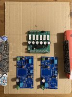
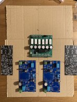
C. For reference, i attached 2 pictures of cardboard & PCB possible arrangement. Cardboard has annotation for 300mm length and 400mm as well.
Input board on the horizontal plate, for easy screwing/unscrewing of M2x daughter boards (don't like to change my M2x board so often for that reason)
Power Channel with Mosfet on the vertical heatsink (1 pic has book to hold them vertical while taking the picture...quick & dirty)
@poseidonsvoice
A. Thanks for the reminder on the front panel & mounting potential. I used it once to have an M2x with a B1K Nutube preamp in it, preamp being mounted on the front panel.
B. Maybe i would put the PS Filter there, need to think a bit about it. & Possibly find a way to have better thermal connection between lateral heatsink and the front panel...But i am already not too happy with the bolts/screw arrangement on a standard chassis, so adding cumbersome stuffs & manage tolerances might not be my cup of tea.
A. Thanks for the example of your Aleph 20 build (now found more pictures here https://www.diyaudio.com/community/...s-chassis-builders-thread.382316/post-7157228) and subjective assessment. That helps getting an idea.
B. In a 3U-300mm, i intend to use the recommended Ship of Theseus external SMPS, freeing up some space and heat (no rectifier inside)
C. For reference, i attached 2 pictures of cardboard & PCB possible arrangement. Cardboard has annotation for 300mm length and 400mm as well.
Input board on the horizontal plate, for easy screwing/unscrewing of M2x daughter boards (don't like to change my M2x board so often for that reason)
Power Channel with Mosfet on the vertical heatsink (1 pic has book to hold them vertical while taking the picture...quick & dirty)
@poseidonsvoice
A. Thanks for the reminder on the front panel & mounting potential. I used it once to have an M2x with a B1K Nutube preamp in it, preamp being mounted on the front panel.
B. Maybe i would put the PS Filter there, need to think a bit about it. & Possibly find a way to have better thermal connection between lateral heatsink and the front panel...But i am already not too happy with the bolts/screw arrangement on a standard chassis, so adding cumbersome stuffs & manage tolerances might not be my cup of tea.
Attachments
@lolo6990 your layout looks good to me. If it's useful, I have a note that the maximum inner width of a 3U/300 at the back plate is 255mm. The drill hole pattern in the bottom plate is set in from the edges so the mounting points are a bit more constrained.
The front panel gets plenty hot. I'd say there's a lot of heat being conducted through and to it.
The front panel gets plenty hot. I'd say there's a lot of heat being conducted through and to it.
Last edited:
@ranshdow
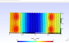
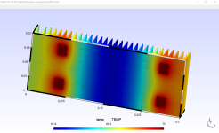
just for the fun of it, a very rough approximation of your 3U-300 Aleph20, from the picture & quick repositionning of transitors/mirroring
1 image is "1 color = 1 degree" with min/max set manually, others are auto-range.
T @vertical of the mosfets is...only 3degrees less than on the mosfet...
just for the fun of it, a very rough approximation of your 3U-300 Aleph20, from the picture & quick repositionning of transitors/mirroring
1 image is "1 color = 1 degree" with min/max set manually, others are auto-range.
T @vertical of the mosfets is...only 3degrees less than on the mosfet...
| | | | | | | |
Attachments
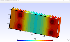
Neat! I wonder if an IR gun would pick up those heat gradients. For reference, each MOSFET is carrying ~750mA and the rails are +/- 21.8V, so assuming 100% of that voltage is dropped across the MOSFETs, I get ~66W/ch. But I want to be careful not to derail this thread further.
I didn't have much success with an IR gun so I bought one of those Amazon DMMs that comes with type-K thermocouples. Along with plenty of Kapton tape, thermocouples seemed to give repeatable measurements with decent accuracy.
I also trid one of those infrared camera adapters that plugs into your smartphone (so the camera doesn't need to have its own display). It made pretty pictures, but I've been warned by physicists that their accuracy is questionable. Something along the lines of, "emissivity is not the same as X, and X is not the same as Y, and Y is not the same as temperature." Using physics words that I've since forgotten. But the general color gradients / heat gradients it displays, are reasonably good. Just not the final degrees-C numbers.
I also trid one of those infrared camera adapters that plugs into your smartphone (so the camera doesn't need to have its own display). It made pretty pictures, but I've been warned by physicists that their accuracy is questionable. Something along the lines of, "emissivity is not the same as X, and X is not the same as Y, and Y is not the same as temperature." Using physics words that I've since forgotten. But the general color gradients / heat gradients it displays, are reasonably good. Just not the final degrees-C numbers.
I originally asked if a Theseus with 3U 300mm would be Ok for thermal.
I went if 1 method to have a guess.
Electrical datas from Mark and you provide possibly another way to look at the problem and assess. Will try that to learn for myself, report back in a while.
Anyways, time line to put everything in the final chassis: 1year!
It is somehow knowledge gained on this amp & chassis
(Degrees of the calculation are just for comparison in the same condition. Not accurate in absolute term for sure)
This thread has comparatively few readers, and I notice that extremely few heat transfer experts post here / read here.
Since your goal is to learn more about heat transfer and dissipation limits, I recommend you find different Forum threads where a whole lot of members with deep expertise in heat transfer problems, post frequently. You'll have a better chance of finding somebody who knows your problem domain deeply, and who definitely knows what they're doing. I personally don't have any idea where or what those threads are, except I'm almost certain they don't include the word Theseus in their title.
Since your goal is to learn more about heat transfer and dissipation limits, I recommend you find different Forum threads where a whole lot of members with deep expertise in heat transfer problems, post frequently. You'll have a better chance of finding somebody who knows your problem domain deeply, and who definitely knows what they're doing. I personally don't have any idea where or what those threads are, except I'm almost certain they don't include the word Theseus in their title.
Gentlemen. I need your advise…
I have been working on the PSFILT board for my p channel vfet for the last week or so. Once stuffed I have been trying to install it in the amplifier.
These are the facts:
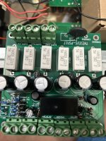
1. After stuffing and cleaning with alcohol and checking all the solders with a magnifying glass and polarities of caps, zeners,, diodes, etc. the board was connected to the power supply and switch only. I do not want to affect the other boards in the amp.
2. Once turned on, there was a series of clicking noises which I gather are related to the delay timer, which has a jumper in its 5 sec posts. Maybe I am wrong about this.
3. Then, there was a thud -more like a small explosion- and the 33 uf cap started to smoke and got very hot, so proceeded to turn it off. So I did not have a chance to measure anything.
4. I am more interested in the power supply aspects of the board, not really on the delay of turn on, and wondering if this aspect of the board can be omitted or bypassed.
5. Of concern also is the fact that the Led was not lighting up. It is the led I have had in the unit, a blue one.
6. Including 2 photos.
Any suggestions will be appreciated
I have been working on the PSFILT board for my p channel vfet for the last week or so. Once stuffed I have been trying to install it in the amplifier.
These are the facts:
1. After stuffing and cleaning with alcohol and checking all the solders with a magnifying glass and polarities of caps, zeners,, diodes, etc. the board was connected to the power supply and switch only. I do not want to affect the other boards in the amp.
2. Once turned on, there was a series of clicking noises which I gather are related to the delay timer, which has a jumper in its 5 sec posts. Maybe I am wrong about this.
3. Then, there was a thud -more like a small explosion- and the 33 uf cap started to smoke and got very hot, so proceeded to turn it off. So I did not have a chance to measure anything.
4. I am more interested in the power supply aspects of the board, not really on the delay of turn on, and wondering if this aspect of the board can be omitted or bypassed.
5. Of concern also is the fact that the Led was not lighting up. It is the led I have had in the unit, a blue one.
6. Including 2 photos.
Any suggestions will be appreciated
Attachments
Would a 5U x 250 modushop heat sink be enough heat sink for this amp? The original vfet one was a 4U 300, right? I know it is set up to use a 36V SMPS, but if we were to use a linear PS what ranges could we operate at 36V? Would a 300VA transformer work in a dual mono orientation with each secondary feeding a positive regulator?
Ship of Theseus is backwards compatible with both of the diyAudio Store VFET amps sold by Lottery (i.e. both the Pchannel and the Nchannel VFET amps). So it's a good idea to read about those on the Firstwatt site. Since post #351 indicates there might be confusion about the double pole switch, I'm providing this (link) to the Nch VFET manual by Nelson Pass, which includes the diagram#1 attached below.
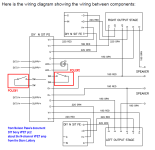
The Nch VFET manual also includes a wiring diagram for the amplifier as a whole, including the two separate poles of the switch. It is attached as diagram#2 below.
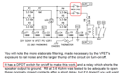
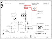
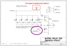
Then the Ship Of Theseus PSFILTer schematics are attached, since Forum members might not have committed them to memory forever. The two poles of the switch are indicated in red. Also there is only one 33uF capacitor on the board (mentioned in post #351), circled in violet.
_
The Nch VFET manual also includes a wiring diagram for the amplifier as a whole, including the two separate poles of the switch. It is attached as diagram#2 below.
Then the Ship Of Theseus PSFILTer schematics are attached, since Forum members might not have committed them to memory forever. The two poles of the switch are indicated in red. Also there is only one 33uF capacitor on the board (mentioned in post #351), circled in violet.
_
Attachments
Probably.Would a 5U x 250 modushop heat sink be enough heat sink for this amp?
Yes.The original vfet one was a 4U 300, right?
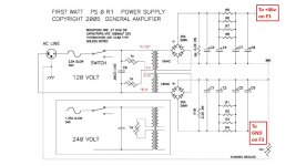
I have a Ship of Theseus running with a linear power supply using a single 300VA transformer. The power supply is a First Watt clone originally used in an F3, so it's a CRC as shown in the attachment, but with secondaries at 28VAC. It needs to be fully loaded by the amp before the rails drop to 36V. I'm not using a filter board between the linear PSU and the amp, just CRC filtering.I know it is set up to use a 36V SMPS, but if we were to use a linear PS what ranges could we operate at 36V? Would a 300VA transformer work in a dual mono orientation with each secondary feeding a positive regulator?
My subjective impression is that there is 1) more hum than with the SMPS and PS filter combo, and 2) the power-on thumping is more prominent with the linear supply versus the filtered SMPS. There seems to be two pulses or waves of cone movement. With little drivers it's a bit scary but I'm not that concerned with my 2-ways.
I've been listening to this amp a while now with Hornet front end cards and I'm reluctant to change the power supply. It sounds really good to me.
Attachments
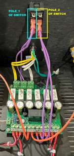
Re: SWITCH in #358
It appears that the right hand pole of the switch is connected to the "SwitchP1" euroblock connector on PSfilt using brown wires. That looks correct.
It also appears that the left hand pole of the switch is connected to the "SwitchP2" euroblock connector on PSfilt using green wires. That also looks correct.
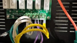
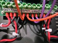
When I built my Theseus amp, I made thermal transfer labels for each of the euroblock connectors, just to help me remember which wires go where. These were shown in post #67 of this thread, and the three photos attached below.
_
It appears that the right hand pole of the switch is connected to the "SwitchP1" euroblock connector on PSfilt using brown wires. That looks correct.
It also appears that the left hand pole of the switch is connected to the "SwitchP2" euroblock connector on PSfilt using green wires. That also looks correct.
When I built my Theseus amp, I made thermal transfer labels for each of the euroblock connectors, just to help me remember which wires go where. These were shown in post #67 of this thread, and the three photos attached below.
_
Attachments
See schematics attached to post #353
1. The explosion of C7 obviously means you must replace C7. Very likely when C7 was dying, it managed to kill both ZD1 and Q1. Replace them too (see next item)
2. If somehow the different voltage-rated Zener diodes got soldered in the wrong places, that wrong arrangement could produce the observed erratic relay behavior with lots of electromagnetic activations and de-activations. I recommend removing all four Zener diodes and carefully replacing them, one by one, from the correct Mouser parts bag with the correct voltage printed on it. In the correct orientation.
3. Only one jumper / shorting block needs to be plugged in. Certainly don't plug in more than one (or all five!). Put it in the "5 second" spot and sleep soundly.
4. After the PCB is removed from the amp (for soldering), use your DVM on "continuity test" mode to verify there are no short circuits between any of the nodes in all high-current paths.
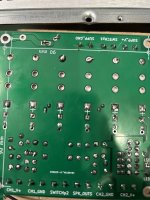
5. The photo of the bottom side of your PCB {post #351} appears to show a cold solder joint. Just above the silkscreen text "CH2_GND" , the negative terminal of capacitor C7 seems to have a weird (cold?) solder joint. This might be either the cause, or the effect, of C7's explosion.
6. If you have one cold solder joint, it's quite likely that you have more than one. Consider heating up every solder joint on the board and letting it reflow. For example the "slot" leg of the inrush current limiter ("thermistor"), need A LOT MORE solder.
1. The explosion of C7 obviously means you must replace C7. Very likely when C7 was dying, it managed to kill both ZD1 and Q1. Replace them too (see next item)
2. If somehow the different voltage-rated Zener diodes got soldered in the wrong places, that wrong arrangement could produce the observed erratic relay behavior with lots of electromagnetic activations and de-activations. I recommend removing all four Zener diodes and carefully replacing them, one by one, from the correct Mouser parts bag with the correct voltage printed on it. In the correct orientation.
3. Only one jumper / shorting block needs to be plugged in. Certainly don't plug in more than one (or all five!). Put it in the "5 second" spot and sleep soundly.
4. After the PCB is removed from the amp (for soldering), use your DVM on "continuity test" mode to verify there are no short circuits between any of the nodes in all high-current paths.
5. The photo of the bottom side of your PCB {post #351} appears to show a cold solder joint. Just above the silkscreen text "CH2_GND" , the negative terminal of capacitor C7 seems to have a weird (cold?) solder joint. This might be either the cause, or the effect, of C7's explosion.
6. If you have one cold solder joint, it's quite likely that you have more than one. Consider heating up every solder joint on the board and letting it reflow. For example the "slot" leg of the inrush current limiter ("thermistor"), need A LOT MORE solder.
Last edited:
- Home
- Amplifiers
- Pass Labs
- Ship Of Theseus: compatible, interchangeable amplifier modules