Long story. Got this vintage class-D amp with a borked power supply. After fixing the issue it went back to the agent who requested the repair. Fully functional. Its owner then requested a recap which the experienced agent duly executed. At powerup (on DBT) it went full latch-up. Sheepishly the agent (who shall remain nameless) came back to me after finding nothing amiss.
After two months breaking my teeth on it I found that the latchup is caused by the SITs not being switched off fully at powerup. Without the output transistors and the PWM in service mode (R119/69) it works like a charm. Now the latchup causes the power supply to be overloaded. Which is weird given that it would work fine with DBT previously. With the PSU overloaded the two gate supply rails (+/-120 V) don't rise enough to cut off the SITs. Which need more than 25 V to reach that point. I also found that the PWM modulator also goes in a latchup mode due to the current source Q103/53 not starting as its power rail also rises too slowly. I did manage to get it going by removing C155 (I am working on the right channel, left is still in service mode) and using an external power supply to get the gate supplies going. At first it would start reliably when switching on the external PSU but when I started to move SITs around that went south and now it is bursting or even flatlining fully latched up. I don't believe that the SITs are bad. The rush-in current limiters are both OK and when the amp does work properly get shorted with their respective relays. Apart from the plethora of PSU rails the circuit itself is not all that complicated but the chicken/egg situation has me utterly flummoxed. What is going on here and how can I fix it? It must be something silly that I am overlooking but for the love of all that's holy I can't see it.
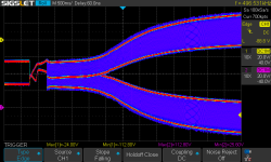
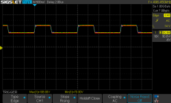
Scope images might illustrate. This is the gate drive of the SITs. This is a successful start with the external PSU:
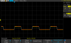
And here it fails:
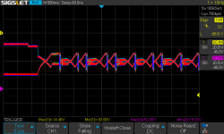
Once the PSU rails are established the rushin relays kick in, followed by the speaker protect relays. The slow rise is caused by the first stage of the PSU, which builds the primary regulated voltage (240 VDC). This is then fed to the second stage which provides mains isolation and all the secondary voltage rails. There are no less than eight. The PSU has not been touched, only the amp itself has been recapped.
After two months breaking my teeth on it I found that the latchup is caused by the SITs not being switched off fully at powerup. Without the output transistors and the PWM in service mode (R119/69) it works like a charm. Now the latchup causes the power supply to be overloaded. Which is weird given that it would work fine with DBT previously. With the PSU overloaded the two gate supply rails (+/-120 V) don't rise enough to cut off the SITs. Which need more than 25 V to reach that point. I also found that the PWM modulator also goes in a latchup mode due to the current source Q103/53 not starting as its power rail also rises too slowly. I did manage to get it going by removing C155 (I am working on the right channel, left is still in service mode) and using an external power supply to get the gate supplies going. At first it would start reliably when switching on the external PSU but when I started to move SITs around that went south and now it is bursting or even flatlining fully latched up. I don't believe that the SITs are bad. The rush-in current limiters are both OK and when the amp does work properly get shorted with their respective relays. Apart from the plethora of PSU rails the circuit itself is not all that complicated but the chicken/egg situation has me utterly flummoxed. What is going on here and how can I fix it? It must be something silly that I am overlooking but for the love of all that's holy I can't see it.
Scope images might illustrate. This is the gate drive of the SITs. This is a successful start with the external PSU:

And here it fails:

Once the PSU rails are established the rushin relays kick in, followed by the speaker protect relays. The slow rise is caused by the first stage of the PSU, which builds the primary regulated voltage (240 VDC). This is then fed to the second stage which provides mains isolation and all the secondary voltage rails. There are no less than eight. The PSU has not been touched, only the amp itself has been recapped.
Some additions for other forum members to participate.
The ServMan of the Sony TA-N88 is 48MB, just to large to post here completely.
The ps-page was in need of some brightness & contrast adjustment (small portion left original).
As is visible in the second picture, the supply tries to start continuously, but fails to engage oscillation.
Do you have this ServMan Regenpak? Drop me a pm.
Attachments
Yes it did. That is the weird part. The recapper is adamant he did not touch the PSU but I am starting to doubt this. Running the PSU on DBT will hinder its capability to charge the capacitors but in this case it seems excessive. It is certainly not (yet) in regulation as there is 100 Hz ripple on the power rails. Changing the bulb to a heavier one (100 W, recapper used 150 W) does nothing to improve however and I am loath to try without DBT out of fear of destroying unobtanium SITs.After the power supply was fixed, did it start up properly on the DBT?
There's no guarantee that it would.
I do. And I have extracted some images like you did as well. Luckily the version I found is a very good scan. I will study your versions. Many thanks!Do you have this ServMan Regenpak? Drop me a pm.
Last edited:
Further analysis.
The ServMan I have has a second section about the 88/88B with more clear pictures. The above is from the first about the 88 only.
The long story:
But also: the smps is able to cope with 120Vac (US) and 220/240Vac (AEP/UK) models without voltage selection switches...
Did it work with a DBT previously? Really?
I would try to fit dummy loads on the D and S connections of the V-fet's to mimic a proper load (in service mode!). If the supply act according to spec's, both the smps and the pwm amps are ok.
I have some thoughts about your SIT's...
The ServMan I have has a second section about the 88/88B with more clear pictures. The above is from the first about the 88 only.
The long story:
Why was is broken in the first place? Information available?Got this vintage class-D amp with a borked power supply.
V-fet's ("SIT's") in this configuration don't like that. If a substantial current is drawn during startup, the bulb can glow bright but taking away some primary voltage from the smps. The +/-120Vdc lines may not come to full power.At powerup (on DBT) it went full latch-up.
But also: the smps is able to cope with 120Vac (US) and 220/240Vac (AEP/UK) models without voltage selection switches...
The +/-120Vdc rails should come up instantly to make this happen.caused by the SITs not being switched off fully at powerup.
There is no substantial load on the +/-78Vdc rails, the (other) rails perform according to specs.Without the output transistors and the PWM in service mode (R119/69) it works like a charm.
That latchup with the V-fet's in place? That could cause an overload.Now the latchup causes the power supply to be overloaded. Which is weird given that it would work fine with DBT previously. With the PSU overloaded the two gate supply rails (+/-120 V) don't rise enough to cut off the SITs.
Did it work with a DBT previously? Really?
That's from the +17/-9.6 rails, also to low due to the overload. The smps will try to correct that (feedback coil 3-4), R413, C406, C405 (u47/50 -> check that one!), within it's designed limits.... also goes in a latchup mode due to the current source Q103/53 not starting as its power rail also rises too slowly.
That's over D151 (MV12N, it could be a suicide diode, but then it breaks) or C155 (u47/50) itself; also check.I did manage to get it going by removing C155
So with an external PS the same thing happens! The smps should be ok.At first it would start reliably when switching on the external PSU but when I started to move SITs around that went south and now it is bursting or even flatlining fully latched up.
Make sure that is not an assumption.I don't believe that the SITs are bad.
I would try to fit dummy loads on the D and S connections of the V-fet's to mimic a proper load (in service mode!). If the supply act according to spec's, both the smps and the pwm amps are ok.
I have some thoughts about your SIT's...
The SITs are not bad. I have only two in circuit (of the eight) and they test correctly with an external power supply. The cutoff voltage for these transistors is very high, some 25 V for both P- and N-channel transistors. That's why Sony needed the +/-120 V rails on top of the +/-78 V main power rails.
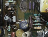
The initial fault was bad resistors and capacitors in the startup circuit for the PSU. I replaced some fried resistors as well:
The PSU came to life perfectly with DBT once this was fixed.
The initial fault was bad resistors and capacitors in the startup circuit for the PSU. I replaced some fried resistors as well:

The PSU came to life perfectly with DBT once this was fixed.
This is not true. The 120 VAC version has a different T402 than the 230 VAC version. The live part generates 106 VDC (US version) or 240 VDC (EU (AEP/UK) version). But the main problem is that the 240 V gets loaded too heavily and is unable to provide the plethora of supply rails with the correct voltage. The cause is of course the DBT but as said the power rating of the bulb does nothing to change this behavior. Whereas with a 60 W bulb it started up without any issue before the recap. The PSU even has its own "DBT" built-in: surge current limiters TH401 and -2 which gets shorted out once the power rails have developed enough voltage to energize relays RY401-2.But also: the smps is able to cope with 120Vac (US) and 220/240Vac (AEP/UK) models without voltage selection switches...
D151 was replaced during the recap with two 1N4148s. Both have the same forward voltage (1.4 V). C155 was a film capacitor. Removal brought back some life as illustrated. With it in place it consistently would go into latchup mode.That's over D151 (MV12N, it could be a suicide diode, but then it breaks) or C155 (u47/50) itself; also check.
And how do they test with a dvm, both the channel (d-s or s-d) and the gs diode?they test correctly with an external power supply. The cutoff voltage for these transistors is very high, some 25 V for both P- and N-channel transistors. That's why Sony needed the +/-120 V rails on top of the +/-78 V main power rails.
The high Vpo is known, in several grades. The same applies for the 5650/4650 amps by Sony.
All around Q408. R479 is connected to the drive bobbin.bad resistors and capacitors in the startup circuit for the PSU
All right, I did not peek into such detail in the ServMan yet. But then a DBT makes even more difference to the smps behaviour.The 120 VAC version has a different T402 than the 230 VAC version.
Ok.But the main problem is that the 240 V gets loaded too heavily and is unable to provide the plethora of supply rails with the correct voltage. The cause is of course the DBT but as said the power rating of the bulb does nothing to change this behavior. Whereas with a 60 W bulb it started up without any issue before the recap. The PSU even has its own "DBT" built-in: surge current limiters TH401 and -2 which gets shorted out once the power rails have developed enough voltage to energize relays RY401-2.
The primary 240V gets overloaded because of the DBT in series...? But Th401 act as such too indeed, so why a DBT is a no go, and Th401 is designed for it!
The relays Ry401 and Ry 402 are supplied by the low voltage (+17/-9.6) rails. If these rails are to low, the relays will not switch. Your chicken/egg situation.
That's very curious...C155 was a film capacitor. Removal brought back some life as illustrated. With it in place it consistently would go into latchup mode.
It's not on the -9.6Vdc rail, there's anoter supply circuit involved around Q312 (Q310, D303, R310, C306, C308), connected to the -9.6 rail. Lots of exclamation marks with these components. Something wrong there? It serves both channels.
If current source Q153 does not reach the proper value, will the pwm amplifier (as a stable circuit) work?
Amp & supply (N88B) extracted from the ServMan.
Attachments
No, it won't. The PWM output will go negative while it should go positive. Or rather, start modulating the 500 kHz carrier. This will switch on the wrong FET but because the +/-120 V rails are way too low the other SIT also conducts leading to the latchup condition. As you correctly state, classic chicken/egg.If current source Q153 does not reach the proper value, will the pwm amplifier (as a stable circuit) work?
Will study your elaborate reply in more detail tomorrow. Thanx so far!
There is a new development. I tested behavior with a dummyload across the +/-78 V power rails. Big fat 470R resistor. Did not reveal much. With a 100 W bulb it took a long time for the voltage to reach +/-50 V. Not regulated but substantially higher than with the SITs in place. The two thermistors were switched out of circuit due to the relays energizing despite the low voltage. This did not make much of a difference as their resistance had dropped due to their heating up. On the secondary thermistor only 2 V were left before the relay eventually kicked in. Without DBT the PSU developed its design voltages immediately.
Then a capacitor (C418) blew up. This is a small cap that is connected across the +77 V line. This line is only 1 V lower than the positive power rail (+78 V) and is needed for the SIT drive circuit. It should never blow with only 1 V across it so this needs some investigation. As I never checked the +77 V line and its negative sister the fault could lie here. I considered power draw without SITs a bit high from the start. Dunno the exact value, some 40 W I think.
To be continued...
What is the end value with the fet's in place?it took a long time for the voltage to reach +/-50 V. Not regulated but substantially higher than with the SITs in place.
That's good news.Without DBT the PSU developed its design voltages immediately.
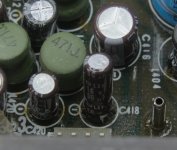
47u/10V between the +78V power rail and the lower +77V gate drive circuits.Then a capacitor (C418) blew up.
Can be wrongly replaced? Aged? D413 ok?
If space permits I'd replaced both C417/418/419/420 with 50V tropic grade types.
Or have a look at Q203/204/253/254 & fusable resistors R207/257.
About 35 V.What is the end value with the fet's in place?
It was installed correctly:Can be wrongly replaced? Aged? D413 ok?
It must be an issue on the amp board as it worked flawlessly before the recap. Something like a tin whisker or somesuch. As I did not look at the +-/77 V rails it could very well be that the fault has been introduced there. I have to muster courage to delve into that (and replace C418).
That's near half way... call it a soft short.About 35 V.
Some thoughts: if one of Q203/204 (253/254) is not ok, that +77V rail can go up by the voltage between Q109/110 (159/160) +96V (35V types should cope whit that though), or some path towards the fets, pulling it down (reversing maybe)...an issue on the amp board
Replace the cap, disconnect the amps and see if the ps works as expected. Connect the amps again, the worst that can happen is another blown C418.
But that +/-35 is worrying serious.
Absolutely. Your procedure is exactly what I had in mind. I did check the drive without SITs and it was fine:But that +/-35 is worrying serious.
But looking at those screenshots now those voltages are too low. They should be +/-77 and +/-120 V. This is the gate drive for the SITs (TP5 and 6). I feel those 1 V offset rails is an ugly kludge by the Sony engineers at the time. No clue what they were trying to solve... Those gate diodes should never go into conduction so that 1 V doesn't make any sense whatsoever.
And are only reaching +/- 70 and +/-108 instead. That's minus ~10% for both. This is without the fet's, not?They should be +/-77 and +/-120 V.
So with 'service mode' enabled, there's no proper feedback. I'd say somewhat squeezed. I don't think that's the core of the problem, it's a response to the s-mode.
To prevent the drivers at these weird rails from latching up? And they are driven to those rails. It's 'digitized'.so that 1 V doesn't make any sense
Observe diodes 203/204/205/206 (253/254/255/256) to 'help this from happening, but notice R204/212 (254/262) which are connected in parallel. The lifeboat is not 100% waterproof.Those gate diodes should never go into conduction
Considering the 'soft-short', the fet's themselves are without any protection whatsoever (no Rs, both just in parallel). If only one...
You're absolutely sure all the fet's are ok (#6)? With the fet's in place, both the ps and the dc sources (D151 @ #8, Q312 @ #9, last remark) behave strange.
The +/-78V rails are the true 'power rails', so if these are roughly at 50%, something is drawing a lot of current, and heating up.
The SITs differ but that is because of V(gs) spread, even though they have the same ranking:The +/-78V rails are the true 'power rails', so if these are roughly at 50%, something is drawing a lot of current, and heating up.
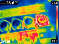
I now test with only a pair in place and even then I get different results as I swap SITs.
The PSU has been fixed and now I will concentrate on the +/- 77 V rails.
One would expect the middle ones to heat up most, not the one on a side with such a difference, even 'spreadwise'.The SITs differ but that is because of V(gs) spread, even though they have the same ranking:
I tested the same ranked SITs on my µTracer 6 and they differ very significantly:One would expect the middle ones to heat up most, not the one on a side with such a difference, even 'spreadwise'.
In the fault condition the transistors are in their linear operating area which means that the transistor with the lowest V(gs) (here #3) carries all the current. With the amplifier in class D this obviously doesn't happen.
- Home
- Amplifiers
- Solid State
- Stuck with Sony TA-N88B
