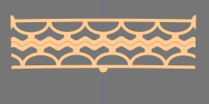
I guess this is better. One thing to look for on this one is that when a half circle is compressed it looks like it will expose and non linear resistance as you approach xmax. Why - because the only way the material close to where the neighbour half circle meets can go, is sideways. But it can go sideways because the neighbour is also bulging (yellow star)... i.e. stiffness increases.,,, This is what an ordinary spider also do but in a different way - the accordion structure is stretched to exhaustion.

Maybe a little distance between the base (at/above the yellow star) of the half circles?
//
Maybe a little distance between the base (at/above the yellow star) of the half circles?
//
Maybe a little distance between the base (at/above the yellow star) of the half circles?
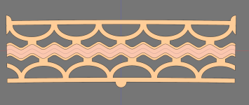
Like this?

I also added a red representation of the peak-to-peak xmax of +- 0.5 mm which is roughly what I aim for. But in practice I'd be content as long as I get +- 0.15 mm with minimal distortion.

The current design has a mechanical xmax between the magnets of +- 1.5 mm.
did you make multiple separated coils you can attenuate ? only possible when going horizontal coils ?
I havent gotten that far yet. But yes, that would be one of benefits of of that design.
Aha. That makes sense.
And I just realized something: It is not enough to just compress each side up to the xmax but ideally the other side should push up to xmax too.
And I just realized something: It is not enough to just compress each side up to the xmax but ideally the other side should push up to xmax too.
- I make each half say 0.5 mm taller and then compress them slightly when mounting. That should make the membrane require less force to move I think since the compressed potential force of one side can be used to trade for compressing the other?
- They are the same size rougly. But then one side is compressed and the other side is pulled, requires more force to move the suspension thus less efficient?
Last edited:
so the traces move horizontal ? and magnetsLike this?
View attachment 1315061
I also added a red representation of the peak-to-peak xmax of +- 0.5 mm which is roughly what I aim for. But in practice I'd be content as long as I get +- 0.15 mm with minimal distortion.
View attachment 1315069
The current design has a mechanical xmax between the magnets of +- 1.5 mm.
I havent gotten that far yet. But yes, that would be one of benefits of of that design.
As you've been saying @WrineX it would probably be a good idea to try with a horizontal magnet layout too.
A horizontal layout would require very precise alignment of the membrane traces such that they end up exactly in between the magnets. The standard lengthwise layout there can be small offset errors which won't matter since the membrane traces will roughly the same along the whole length.
It does have benefits though, the effective CTC would be far less and in this case I think I should be able to just curve the steel plate and not have to worry about the plate to magnet gap reducing the efficiency. And since the steel would not be segmented it would be a lot stronger.
I've been thinking more about PP or SE with the magnets. I looked again at your thread @WrineX https://www.diyaudio.com/community/...nar-magnetic-both-active-driven.411612/page-9 where you find that there is not a huge difference in distortion in SE vs PP. My current plans are for 3mm thick N52 magnets and 50% of the radiating area covered my magnets, thats a lot of magnet. More than most off the shelf planars. It will probably be crazy efficient and while efficiency is nice it is not my main goal, my main goal is to have a great frequency response. Lets pretend I'm lucky and the driver would be ~ 93 dB efficient @ 1W then a 2-3 dB drop to 90 dB @ 1W is still plenty high enough for my use case.
It would make it easier to manifacture too since I can skip the risky step of forcing the steel-top-with-magnets onto the assembled bottom with magnets.
Attachments
Last edited:
OOh yeah i forgot you wanted to use corrugation  that is indeed hard to do with horizontal magnets, also the traces must be wider or wave patern, so there will be overlap else corrugations might end up between traces here and there,
i like single ended since it measures cleaner but , single ended 93 dB, might be hard to get. i used n35 and i get for a 40cm long one around 86dB at 4 ohm. making them longer hardly adds to the top end so for single ended that might be the limit in spl for my magnets at least. keep in mind you also attenuate quite some bit for shading
  by the way looks like a weird and interesting suspension interesting to see how that works
i like single ended since it measures cleaner
Good to know.
And while I'm at it since I think you have tinkered with this @WrineX
When doing a sideways corrugated membrane, how much of the membrane should I fill with traces? Just routing traces in between the magnets should be the lightest and have traces where the magnet strength is the most linear, but would probably not hold the shape as if I say filled the gaps in between the coils under the magnets with alu foil too. Even if that foil isn't a part of the coil.

So basically, if I want the best efficiency + distortion performance:
(Assume that I've covered the edge under the gasket / suspension with foil since it definently needs the strength there)
1. Only traces in between the magnets like the PT2522?

2. Traces in between the magnets but also fill the gaps under the magnets with unconnected foil for strength?

3. Traces which extend further under the magnets with a small unconnected line in between? Or basically keep the whole membrane covered with foil except for where I need to pull some material around the traces.

And while I'm at it since I think you have tinkered with this @WrineX
When doing a sideways corrugated membrane, how much of the membrane should I fill with traces? Just routing traces in between the magnets should be the lightest and have traces where the magnet strength is the most linear, but would probably not hold the shape as if I say filled the gaps in between the coils under the magnets with alu foil too. Even if that foil isn't a part of the coil.

So basically, if I want the best efficiency + distortion performance:
(Assume that I've covered the edge under the gasket / suspension with foil since it definently needs the strength there)
1. Only traces in between the magnets like the PT2522?

2. Traces in between the magnets but also fill the gaps under the magnets with unconnected foil for strength?

3. Traces which extend further under the magnets with a small unconnected line in between? Or basically keep the whole membrane covered with foil except for where I need to pull some material around the traces.

I did some more thinking about the horizontal magnet setup.
With a corrugated foil it is almost a recipe for disaster since so many things must be just right for it to work. But what if I instead in that setup used a conventionally tensioned membrane? The old BG Neo8S has a 9 cm wide frame with a 7 cm wide membrane and it can play down to 400 hz and has a tensioned membrane. So in theory I should be able to copy those dimensions but just extend the driver from 20 cm tall to 160 cm. A big benefit too would probably be that the gasket / suspension wouldn't be needed.
So that got me thinking of the feasibility of making a tensioned membrane. I see the following problems / engineering challenges:
But most importantly, even if I could somehow get it to work: would it be superior to the untensioned corrugated design with the slightly unconventional suspension?
With a corrugated foil it is almost a recipe for disaster since so many things must be just right for it to work. But what if I instead in that setup used a conventionally tensioned membrane? The old BG Neo8S has a 9 cm wide frame with a 7 cm wide membrane and it can play down to 400 hz and has a tensioned membrane. So in theory I should be able to copy those dimensions but just extend the driver from 20 cm tall to 160 cm. A big benefit too would probably be that the gasket / suspension wouldn't be needed.
So that got me thinking of the feasibility of making a tensioned membrane. I see the following problems / engineering challenges:
- How can I consistently tension such a long membrane? How can I ensure it is evenly tensioned along the whole length? It would be easier to build it in segments but to avoid lobing I would prefer to have a single long membrane.
- I guess for the best results the membrane tensioning jig should have the same curve as the driver? What would such a tensioning jig look like?
- How would I keep the tension afterwards?
- I guess having a large steel frame to glue the membrane to would work. Would need to have the same curve as the driver but that sounds doable.
- Or could I somehow mount the membrane first untensioned and then apply the tension after the driver is assembled? Would let me tune the resonance evenly across the whole driver but would need some fancy tensioning solution.
But most importantly, even if I could somehow get it to work: would it be superior to the untensioned corrugated design with the slightly unconventional suspension?
A wonder if not the practical implementation aspects are the strongest forces here... your last question - I think you need to prototype that on order to get an answer. A two segment driver should be enough to get the desired insight?
Exactly. I plan to start with the corrugated designs mainly because I believe they are more practical to build.
With the corrugated design I believe it would be trivial to build a tall design since it isn't tensioned. So I plan to build 20 cm tall prototypes and then compare the prototypes to a GRS Neo8 clone which is my reference. If I can get max SPL, efficiency and distortion performance comparable or better than the Neo8 clone then I would rate the prototype a success.
Eventually yes, but that requires me to first decide what dimension of magnets I want to use and order a large batch of them. Currently I only have small magnets for two 20 cm tall drivers:
To ensure I compare apples to apples when comparing to the GRS Neo8 clone I might tweak some parameters and do away with the curve such that they are flat. My first goal is to see if my planar design makes sense or if there are any glaring issues I need to fix first. After I have established that I can start adding the curve.
I just ordered steel plates for both the 5 rows of 5x3mm magnets and 7 rows of 5x4mm magnets from Fractory. The 5 row would have a radiating width of 40mm and a total width of 80mm. The 7 row would be slightly wider at 52mm radiating width and 90mm total width.
- 5 rows of 5x3mm magnets
- 7 rows of 4x3mm magnets
To ensure I compare apples to apples when comparing to the GRS Neo8 clone I might tweak some parameters and do away with the curve such that they are flat. My first goal is to see if my planar design makes sense or if there are any glaring issues I need to fix first. After I have established that I can start adding the curve.
I just ordered steel plates for both the 5 rows of 5x3mm magnets and 7 rows of 5x4mm magnets from Fractory. The 5 row would have a radiating width of 40mm and a total width of 80mm. The 7 row would be slightly wider at 52mm radiating width and 90mm total width.
2 and 3 gives the most stability between connected foils but also more non driven mass that might resonate.Good to know.
And while I'm at it since I think you have tinkered with this @WrineX
When doing a sideways corrugated membrane, how much of the membrane should I fill with traces? Just routing traces in between the magnets should be the lightest and have traces where the magnet strength is the most linear, but would probably not hold the shape as if I say filled the gaps in between the coils under the magnets with alu foil too. Even if that foil isn't a part of the coil.
View attachment 1317037
So basically, if I want the best efficiency + distortion performance:
(Assume that I've covered the edge under the gasket / suspension with foil since it definently needs the strength there)
1. Only traces in between the magnets like the PT2522?
View attachment 1317040
2. Traces in between the magnets but also fill the gaps under the magnets with unconnected foil for strength?
View attachment 1317041
3. Traces which extend further under the magnets with a small unconnected line in between? Or basically keep the whole membrane covered with foil except for where I need to pull some material around the traces.
View attachment 1317042
It's very hard to simulate the behaviour of the non driven parts of the membrane and it requires a lot of expertise and experience.
I'm afraid that you'll have to find out the hard way; empirical research.
The connected foil should be at lot less than in 2 (or 3!).
In my case I have 5 mm between magnets but only 3 mm of connected foil.
Here's the result of simulations of 2.5 to 9 mm connected foil width:
The deviation at 1 mm excursion is lower than 0.2 % for the 3 mm wide aluminium foil.
Note that you'll need that much Xmax even for a mid or tweeter if the membarne is corrugated.
- Home
- Loudspeakers
- Planars & Exotics
- DIY midtweeter planar, physically curved and shaded to be used in a dipole CBT


