I just got a new batch of Pete Millet's Korg 6P1 NuTube preamp module PCBs in. These fit the Yarra preamp motherboard or the M2X amplifier bolt pattern. This is a valve SE triode design using a compact NuTube vacuum tube design by Korg. The Pete Millet design is used with permission - thank you, Pete! And thank you, JPS64 for a super layout!
More info in the Yarra thread, here.
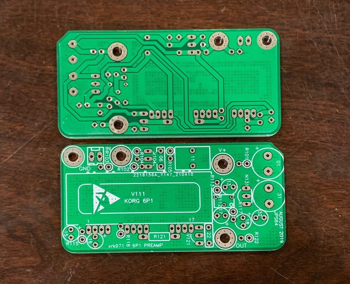
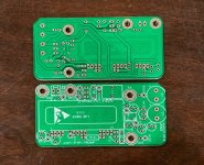
Here is the new green PCB:
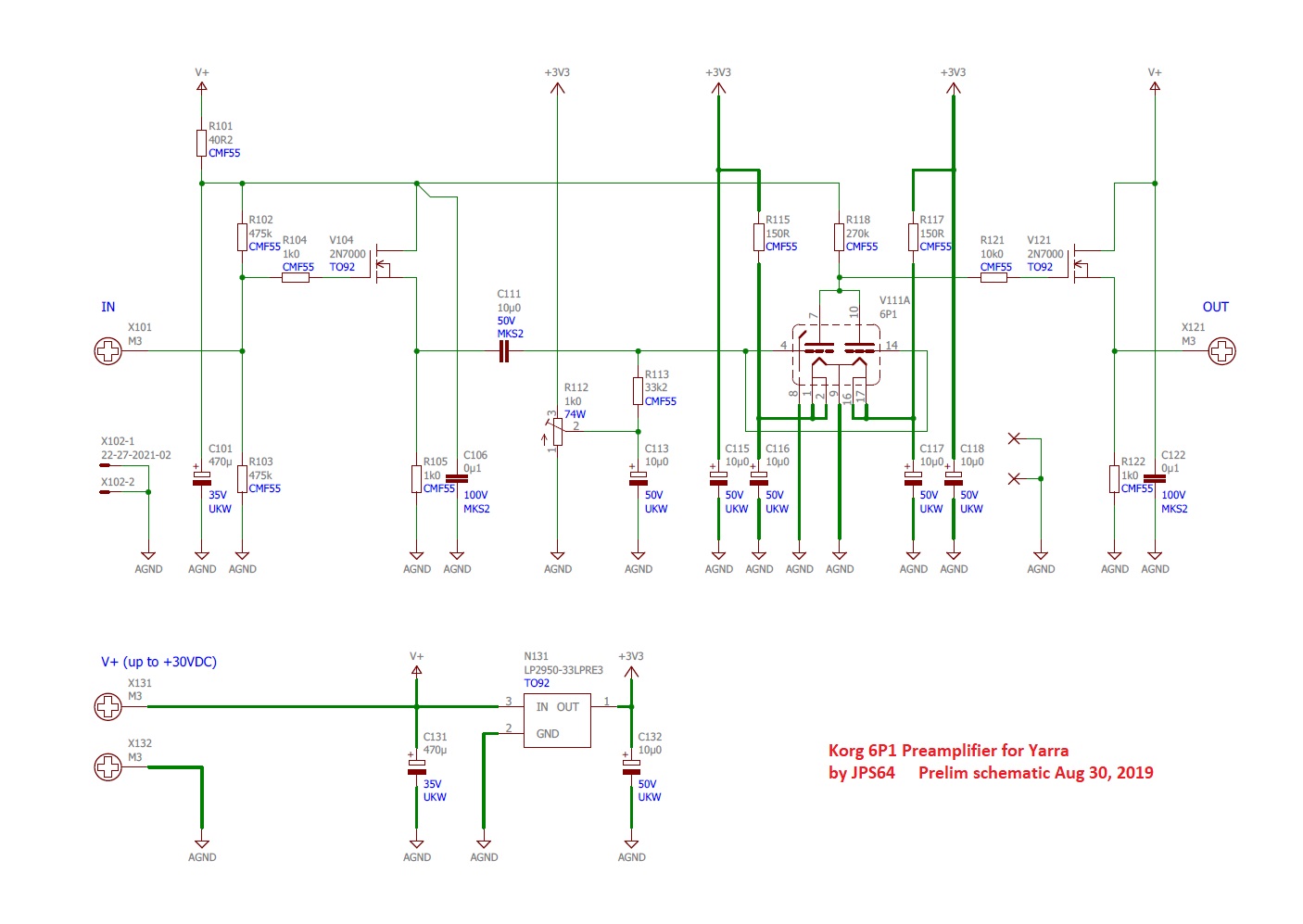
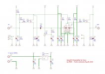
Schematic:
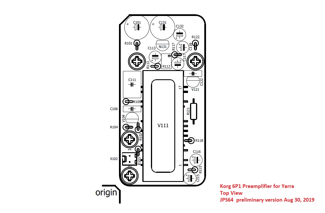
Stuffing Guide:
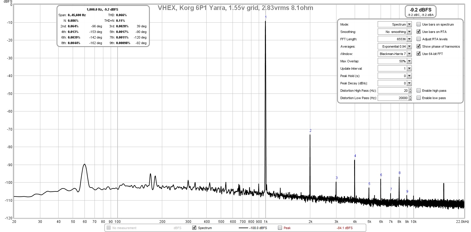
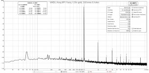
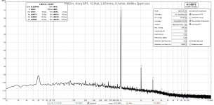
FFT with VHEX+ amp 2.83vrms and 1.55v grid voltage:
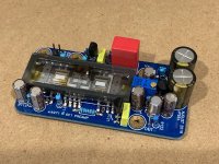
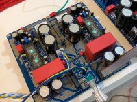
Assembled preamp unit:

Mounted on Yarra motherboard:

The PCBs can be found in my shop here:
Korg 6P1 Preamp for Yarra | Etsy
The BOM in Excel xlsx format is below as .asc file. Rename as .xlsx to open as spreadsheet.
More info in the Yarra thread, here.
Here is the new green PCB:
Schematic:
Stuffing Guide:
FFT with VHEX+ amp 2.83vrms and 1.55v grid voltage:
Assembled preamp unit:
Mounted on Yarra motherboard:
The PCBs can be found in my shop here:
Korg 6P1 Preamp for Yarra | Etsy
The BOM in Excel xlsx format is below as .asc file. Rename as .xlsx to open as spreadsheet.
Attachments
-
 6P1-Korg-PCB-green.jpg480.7 KB · Views: 1,109
 -
 Korg-6p1-Yarra-Schematic-v0.jpg201.3 KB · Views: 1,713
 -
 Korg-6p1-Yarra-Top-Stuffing-Guide-v0.jpg137.6 KB · Views: 1,113
 -
 Korg-6P1-Yarra-test-VHEX-FFT-1.55v-Grid.jpg226.7 KB · Views: 1,060
 -
 Korg-6P1-Yarra-test-build-01.jpg435.4 KB · Views: 1,152
 -
 Korg-6P1-Yarra-test-build-02.jpg461.2 KB · Views: 1,121
 -
Korg-6p1-Yarra-BOM-v0-xlsx.asc18.3 KB · Views: 108
Last edited:
The design is based on this one by Pete Millet (used with permission):
Nutube 6P1 Buffer PCB
He says the gain is 6x.
The board used the same 4 bolts as M2X, although -ve supply is not used and 5th GND bolt is missing on M2X, hence a Molex KK connector is provided for that to be done with a flying lead.
Nutube 6P1 Buffer PCB
He says the gain is 6x.
The board used the same 4 bolts as M2X, although -ve supply is not used and 5th GND bolt is missing on M2X, hence a Molex KK connector is provided for that to be done with a flying lead.
XRK - working up the BOM for the Nutube 6P1 Daughterboard
Only sticking point is the 2N7000 critters. There are plenty of versions with 200ma, but the onsemi orginal is 350ma. Will the 200ma versions work?
Other suggestions if possible. Can the circuit work with 2N3904 transistors, and if so, what other alterations are needed? (I read Pete Millet's comment about this, but the schematics are different enough that I can't be sure)
Looking forward to giving this a try
Thanks
More info on setup here.
https://www.diyaudio.com/community/...or-melbourne-db-group-buy.334457/post-5943697
It’s been quite a while since I set one up. Hopefully someone with a better memory can help out.
IIRC, adjust pot to get grid voltage to 1.63v. Monitor at pin 4. Try to adjust your PSU and resistor above the plate to get 12v at pin 7. I think I had about 28v supply input. This went across 270k ohms at R118 and I got 60uA combined current across both plates (30uA each) and 12v at pin 7.
Last edited:
Grid - top of R113
Plate - top of R118
Might be worth making a big enough loop on those 2 resistors to hook a probe on.
I guess if my PSU is lower (25-26) I would end up changing R118 if it’s too far off. I understand the tubes take a wide range of voltages, 12v has been chosen as best for our purposes?
Plate - top of R118
Might be worth making a big enough loop on those 2 resistors to hook a probe on.
I guess if my PSU is lower (25-26) I would end up changing R118 if it’s too far off. I understand the tubes take a wide range of voltages, 12v has been chosen as best for our purposes?