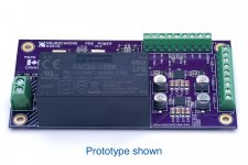
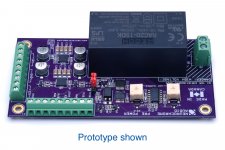
The Preamp Power Supply provides a +/-12 V output and can source up to 650 mA. This Power Supply features ultra-low output noise which makes it an ideal power supply for preamplifiers, headphone amplifiers, phono stages, and buffers such as my Universal Buffer. The ultra-low noise +/-12 V output is also perfect for use with my Purifi 1ET400A / Hypex NC500 Input Buffer and Pufiri/Hypex amplifier modules.
The Preamp Power Supply has the following features:
The power supply is currently in production. I expect to have the first batch of 10 available by the end of July with more to follow around the middle of August.
I am making the Preamp Power Supply available on pre-order special for $139. Once the first batch arrives, the price will increase to $159.
Tom
The Preamp Power Supply has the following features:
- Fixed +/-12 V @ +/-650 mA output.
- Ultra-low output noise and output impedance.
- Mains voltage input with support for worldwide mains voltages and frequencies.
- Integrated power control circuitry which supports the use of low-voltage switches, such as the anti-vandal switches popular with DIYers.
- Support for both momentary (doorbell) and toggle switches for power control.
- Built-in over-current and over-temperature protection on all outputs.
- LED indication of ON and STANDBY states with support for bi-colour LEDs (both 2-pin and 3-pin types).
- Dual LED dimmer.
- 12 V compatible trigger output with 100 mA current limit for remote control of power amplifiers.
- 12 V, opto-isolated trigger input.
- 5 V @ 80 mA always-on auxiliary power supply.
- Rising cage clamp output terminals supporting wires up to AWG 16 (1.5 mm2) in size.
- Compact 55 x 108 mm footprint. Fits within a 1U chassis height, including safety clearances.
- Two-layer, gold plated PCB.
- Made in Canada.
The power supply is currently in production. I expect to have the first batch of 10 available by the end of July with more to follow around the middle of August.
I am making the Preamp Power Supply available on pre-order special for $139. Once the first batch arrives, the price will increase to $159.
Tom
Attachments
Even one of your THAT driver boards?
Sure. Though, you'll want to bypass the regulators on the THAT boards if you go that route. That's pretty easy: Populate the bypass caps but none of the other power supply components. Then connect the power supply to J6.
WHY would you build a preamp power supply at +/- 12 volts instead of industry standard +/- 15 volts? That's already starting off with a 2db penalty in headroom.
Because I wanted the lower noise.
I also wanted to be able to support the Purifi 1ET400A as many are building their own supplies for those amps instead of using Hypex's SMPS. The Purifi requires ±12 V for its opamps.
Headroom is one of those rather meaningless parameters. ±12 V allows for clean reproduction of the 2 V RMS single-ended and 4 V and 8 V RMS differential that are used in audio.
Tom
Last edited:
I was originally planning for ±15 V as it is (one of) the industry standard(s). I was going to use an optimized CLC filter to eliminate the switching noise of the RECOM switching supply.
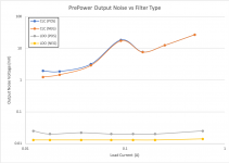
The attached plot shows the output noise voltage with the CLC filter for the positive and negative supply (red and blue traces). Note that the noise increases rather dramatically as the converter changes from discontinuous to continuous mode. The noise is high enough that I worry some of it will couple through to the output of the preamp.
The grey and yellow traces show the output noise when using TI's low-noise LDOs. This is what you'll get with the production version of the Preamp Power Supply.
Note that the axes are logarithmic.
20 uV vs 20 mV noise... vs I know which one I prefer...") And unlike transformer-based solutions, my PrePower is completely free of mains hum.
And unlike transformer-based solutions, my PrePower is completely free of mains hum.
But the LDOs do require some drop-out voltage. I could have settled for some obscure output voltage, like, ±13.5 V. Instead I opted for ±12 V so I could support the Purifi amps. ±12 V is just as much an industry standard as ±15 V. It'll allow for clean reproduction of audio signals at both consumer and professional levels with modern opamps. But, yeah, 12 V is 1.9 dB lower than 15 V. Whoopti-doo.
Tom
The attached plot shows the output noise voltage with the CLC filter for the positive and negative supply (red and blue traces). Note that the noise increases rather dramatically as the converter changes from discontinuous to continuous mode. The noise is high enough that I worry some of it will couple through to the output of the preamp.
The grey and yellow traces show the output noise when using TI's low-noise LDOs. This is what you'll get with the production version of the Preamp Power Supply.
Note that the axes are logarithmic.
20 uV vs 20 mV noise... vs I know which one I prefer...
And unlike transformer-based solutions, my PrePower is completely free of mains hum.But the LDOs do require some drop-out voltage. I could have settled for some obscure output voltage, like, ±13.5 V. Instead I opted for ±12 V so I could support the Purifi amps. ±12 V is just as much an industry standard as ±15 V. It'll allow for clean reproduction of audio signals at both consumer and professional levels with modern opamps. But, yeah, 12 V is 1.9 dB lower than 15 V. Whoopti-doo.
Tom
Attachments
Last edited:
+/-24V rails can be a big deal in pro gear. +/-12 vs +/-15 not so much imo.
Two short questions if I may: iirc, the switching frequency is 100khz in these converters. Was the measured noise with the CLC at this frequency (and harmonics of it) or was it more broadband ? Would you say they are not as good (by themselves) as the Meanwell IRM serie you used in the past ?
Two short questions if I may: iirc, the switching frequency is 100khz in these converters. Was the measured noise with the CLC at this frequency (and harmonics of it) or was it more broadband ? Would you say they are not as good (by themselves) as the Meanwell IRM serie you used in the past ?
What is the output voltage regulation with respect to changing output current?
Static noise measurements and output impedance are meaningless marketing hype if it cannot hold the voltage steady for output current transients. Those data are mysteriously missing from the link you posted.
Static noise measurements and output impedance are meaningless marketing hype if it cannot hold the voltage steady for output current transients. Those data are mysteriously missing from the link you posted.
Two short questions if I may: iirc, the switching frequency is 100khz in these converters. Was the measured noise with the CLC at this frequency (and harmonics of it) or was it more broadband ?
The CLC was designed such that it had minimal impact on the output impedance of the supply while also providing meaningful attenuation at the switching frequency.
The key here is, "meaningful attenuation". Due to the parasitics in the CLC components, you rarely get that much attenuation. You might get 30-40 dB at most, and pushing beyond 20 dB attenuation requires some reading of the data sheets.
You also don't want the CLC to be too peaky as you'll get ringing on the supply rails during transients.
Would you say they are not as good (by themselves) as the Meanwell IRM serie you used in the past ?
To be clear: The RECOM power bricks do meet their specs. As does the Mean Well IRM-series I've used in the past (and still use on some products).
The problem is that ... they meet their specs.
The RECOM appears to use some sort of burst mode at low currents. This causes its ripple voltage to rise. While it is still within the limits in its data sheet, the resulting voltage ripple lands in the audio band under certain conditions. This sort of behaviour is actually fairly common. The manufacturers use burst mode to increase efficiency at light load so they can meet current energy use standards.I did consider using two Mean Well IRM-series, but doing so would have been nearly twice the cost and twice the board area. I wanted a solid module that would basically "disappear" in the chassis. Smaller is better.
Engineering is about tradeoffs. I think I've struck a good balance between price, size, features, and performance. I did weigh performance heavier than the other parameters, though. As you point out, the difference between ±12 V and ±15 V is academic these days. ±15 V (or ±16-17 V) is mostly remnants of legacy opamps that would start to distort if the output voltage was even within a few volt of the supply rails. Modern opamps can swing cleanly at nearly rail-to-rail voltages.
Tom
What is the output voltage regulation with respect to changing output current?
Good question. I don't yet have an answer for you. Based on the LDO data sheets, I'd expect the load regulation to be within 0.3 %Vo.
Static noise measurements and output impedance are meaningless marketing hype if it cannot hold the voltage steady for output current transients.
That's your opinion, which you are entitled to. I still provide vastly more data than anybody else in the DIY community.
Those data are mysteriously missing from the link you posted.
There's no need for innuendo. Did you ever stop to consider that maybe I just hadn't gotten there yet? Or consider that maybe it slipped my mind?
I'll add a transient response measurement to the list, though, I may choose to wait until I have the production version before I conduct that measurement. I prefer to show measured data for the production version as I expect it to perform slightly better than the prototype. I prefer to a) not air my dirty laundry and b) only do the required work once.
Thanks for bringing it up, though. I do agree that a transient response measurement is needed and I will add it at a later date.
Tom
Last edited:
An ignorant question, but it could work, so I'll ask. Can this supply be used as a +24VDC supply. I'm thinking of a preamp application, and I recognize that the -12v, now 0v terminal would have to float from the psu out to the audio out. Is there any way that a power amp with a low impedance connection between signal ground and safety (mains) ground could avoid shorting the psu ouput 0v (+12, 0, -12) and the now 0V (formerly -12) signal ground.
I suppose the followon question is: If it would not short, is this a suboptimal configuration anyway?
Thanks, Skip
I suppose the followon question is: If it would not short, is this a suboptimal configuration anyway?
Thanks, Skip
An ignorant question, but it could work, so I'll ask. Can this supply be used as a +24VDC supply.
I would think so. I don't see any reason it would not work.
The output is not connected to the mains ground.
I suppose the followon question is: If it would not short, is this a suboptimal configuration anyway?
You could probably get lower noise with a dedicated +24 V regulator.
I'll add, "look at performance at +24V operation" to my list.
I would think that one could infer transient performance from the LDOs' datasheet plots of load transients and PSRR.
I agree. Sadly, there's no 15 V in, 12 V out plot in the data sheet. I suspect the performance of the PrePower will be close to that shown in attached data sheet figure, though.
Tom
Attachments
True, though that load transient has far steeper edges than any audio signal is likely to muster. It also depends on the input and output capacitors on the regulator -- the plot you snipped has 10uf and your board has 47uF plus whatever is on the board that the user is powering.
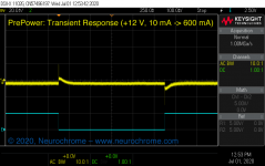
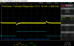
You're in luck. I got curious, so I devised a li'l circuit that allows me to measure the step response of the Preamp Power Supply.
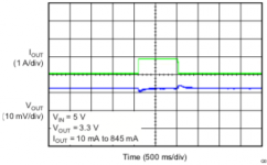
Attached plots show the output voltage of the supply with a 10 mA -> 600 mA step. It looks pretty clean to me. Basically, you get an 8-10 mV disturbance when the load changes from 10 mA to 600 mA and a similar disturbance when it changes back.
As pointed out above, the edge rate here is way beyond anything you'll see in audio, which explains the bit of inductive spike as the current changes.
I also looked at the performance with the supply used as a single +24 V supply. It wouldn't be my first choice for that application as it is a bit noisier than I would like. You might be able to improve on that by adding load from V+ and V- to GND, however.
Tom
Attachments
Last edited:
Thanks for the answer and this information about the practical behavior of the Recom's. I intended to use it pretty much naked but I'll have to rethink that.This causes its ripple voltage to rise. While it is still within the limits in its data sheet, the resulting voltage ripple lands in the audio band under certain conditions. This sort of behaviour is actually fairly common. The manufacturers use burst mode to increase efficiency at light load so they can meet current energy use standards.

- Status
- This old topic is closed. If you want to reopen this topic, contact a moderator using the "Report Post" button.
- Home
- Vendor's Bazaar
- Ultra-Low Noise Preamp Power Supply: +/-12 V, 650 mA