Sonore Lumiere Series - fiber optical i2s send/receive board
These board allows for two-way transmission of standard CMOS 3.3V single-ended signals (i2s/master clock) via a single fiber optic cable.
Signals go from source to destination and concurrently signals go from destination to source.
There is nothing to code and you just connect the inputs and outputs as needed.
These boards guarantee you 100% galvanic isolation between source and destination while transmitting i2s/master clock between your audio products.
Here are some use examples:
1. Send i2s from source to DAC and concurrently send the master clock back to the source.
2. Send i2s and master clock from the source to the DAC.
3. Send the master clock only from the source to a DAC or vice versa.
The conversion chips utilized onboard have a low additive jitter of 30fs which is 100 to 1000 times less than the standard LVDS parts.
These boards utilize standard low noise LT3045 regulators.
These boards have four mounting screws or can be panel mount with standard hardware.
I'm preparing a production run and I'm looking to gauge interest in the project.
Specifications:
95mm x 55 mm
5 VDC input
four +/- send pins
four +/- receive pins
Assembled
Transceiver and fiber cable included
If you are interested please contact me via email at sonorejr@gmail.com with subject = optical i2s.
Last edited:
--- so for instance an Amareno then your board then the Toslink input of a DAC ?
Toslink isn't relevant; this is to send/receive I2S data.
BTW, your signature block isn't really in the spirit of this site announcement;
No Medical Threads
Last edited:
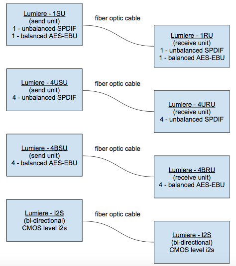
This kind of confusion was expected") Nautibuoy is correct in that you need a send board in the source and receive board in the destination for this to work. However, we are not limited to sending/receiving just i2s and we can just as easily transmit SPDIF and AES-EBU. Just understand that we are not converting to Toslink on these boards.
Nautibuoy is correct in that you need a send board in the source and receive board in the destination for this to work. However, we are not limited to sending/receiving just i2s and we can just as easily transmit SPDIF and AES-EBU. Just understand that we are not converting to Toslink on these boards.
This diagram may help explain things:
Nautibuoy is correct in that you need a send board in the source and receive board in the destination for this to work. However, we are not limited to sending/receiving just i2s and we can just as easily transmit SPDIF and AES-EBU. Just understand that we are not converting to Toslink on these boards. This diagram may help explain things:
Toslink isn't relevant; this is to send/receive I2S data.
BTW, your signature block isn't really in the spirit of this site announcement;
No Medical Threads
I understand , you need two, it's a lttle like the Bufalo transporter principles but here it's i2c or i2s transmited by light so few loss and few jitter....
I have a couple of questions:
How is the maximum distance between send & receiver I2S signals?
How much is the unit price?
TIA
Felipe
Several kilometers
The price is in the air and will depend on interest.So of used the i2s version, could I only use the CLK to transfer only a clock on the opto?
In the sender and receiver, is there *any* reclocking or is it purely signal transfer - almost like sending analog-over-opto?
An other way to see my question.. will there be any jitter introduced/added due to clocks on the boards?
//
In the sender and receiver, is there *any* reclocking or is it purely signal transfer - almost like sending analog-over-opto?
An other way to see my question.. will there be any jitter introduced/added due to clocks on the boards?
//
Pure signal transfer...no clock or reclocking on the board.So of used the i2s version, could I only use the CLK to transfer only a clock on the opto?
In the sender and receiver, is there *any* reclocking or is it purely signal transfer - almost like sending analog-over-opto?
An other way to see my question.. will there be any jitter introduced/added due to clocks on the boards?
//
So at the end, after the receiver, one is needing a reclocker and a fifo cause before the emitter the source will be probably an usb from a pc, a nas ?
I'm trying to understand where it could be usefull? One source perhaps then transport towards several dacs with a multi amp active system? Source to speakers.
TNT sugestion makes sense, you should capture several screens and post them. Jitter at the inputt and just before the light conversion then the same on the receiver side perhaps,,, people needs datas and scenarios.
Many of us like I am are just enthusiasts and don't imagine all the uses.
The only idea I have from the first post is a pc with usb outputt far from the dac. Fiber instead usb cable or hdmi with the advantage of galvanic isolation...jitter seems not relevant cause fifo and reclocking became the rule.
Another idea could be the same for short distance in a dac but with three lines for each i2c or i2s, for the galvanic isolation as well... maybe it can interest more people... I don 't know...just guessing.
Nice!
How much added jitter and with what spectral distribution can we expect on the output?
I would like to place my clocks out of reach for the sound pressure and vibration in my room. I know I have to accept an added amount of phase noise but I think it is OK because it will not be correlated with the music played.
Power feed?
What opto fiber / connectors?
What is the bandwidth supported for payload? Can a 24 Mhz clock be sent?
I'm actually interested.
//
edit: I see I must read better - sorry
Last edited:
Several kilometers
I'm interested but if the price is too high not.
The source can be anything including a CD player. We use to make a DIY USB interface with reclocking on it so no additional reclocking you be needed.So at the end, after the receiver, one is needing a reclocker and a fifo cause before the emitter the source will be probably an usb from a pc, a nas ?
I'm trying to understand where it could be usefull? One source perhaps then transport towards several dacs with a multi amp active system? Source to speakers.
TNT sugestion makes sense, you should capture several screens and post them. Jitter at the inputt and just before the light conversion then the same on the receiver side perhaps,,, people needs datas and scenarios.
Many of us like I am are just enthusiasts and don't imagine all the uses.
The only idea I have from the first post is a pc with usb outputt far from the dac. Fiber instead usb cable or hdmi with the advantage of galvanic isolation...jitter seems not relevant cause fifo and reclocking became the rule.
Another idea could be the same for short distance in a dac but with three lines for each i2c or i2s, for the galvanic isolation as well... maybe it can interest more people... I don 't know...just guessing.
I don’t have the numbers for you yet because we are making a new run, but I very high expectation based on the specs of the parts used.Nice!
How much added jitter and with what spectral distribution can we expect on the output?
I would like to place my clocks out of reach for the sound pressure and vibration in my room. I know I have to accept an added amount of phase noise but I think it is OK because it will not be correlated with the music played.
Power feed?
What opto fiber / connectors?
What is the bandwidth supported for payload? Can a 24 Mhz clock be sent?
I'm actually interested.
//
edit: I see I must read better - sorry
You can have the clocks at the source.
When we get ready to sell these we will provide links to approved fiber cables and transceivers.
These are not expensive, but they will cost less if more people want themI'm interested but if the price is too high not.
So if the clock can be before the emiter, people will want to have jitter measurement at the input of one emiter and the output of a receiver to know the ADDED jitter (if I follow and understand what TNT said) : be it low, cause can help in design decision in a added bricks scenario picking best of breeds.
I like it and, depending on price of course, am in. A few questions:
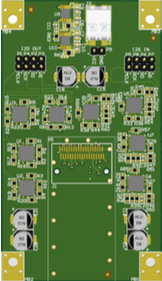
From the PCB image it looks like you’re using an SFP cage. Will there be an option for an open SFP cage and my choice of transceiver? I already run 1Gbase LC fiber to a Roon server.
Which leads to the next question - will it be Roon Ready?
I am assuming that if, like me, the primary source is a server with fiber out to an SFP-equipped switch then all I need do is come out of a second SFP port on the switch with my choice of transceiver to your SFP-cage equipped board and then into the DAC via i2s?
How are you handling the clocking?
The two similar existing offerings I can find don’t tick all the ‘audiophile’ boxes - the Engineered-DOCK ticks all the boxes except it’s too pricey, isn’t Roon Ready and it’s using RJ45 (I exchanged emails with Alexandre re an SFP-equipped backplane but he didn’t seem too interested) and the Conversdigital offering is FastEthernet only, doesn’t do DSD (I think) but it is Roon Ready and affordable. The WiFi option, if one wanted to go that way, is under U$25. Not sure of current pricing but main board was under U$100 awhile back and is used by the likes of Bel Canto and Ayre.
You’d have a winner on your hands, both in the DIY community and OEM if you went with the open cage SFP and Roon Ready tag, DSD256, 32/384 etc. like the DOCK but with SFP in. Fiber is cheap nowadays - Netgear make a 2-port SFP switch for around $140. And it has a 12V input power jack so making your own LPS (Salas L-adapter) ticks that box. I’m even trying to talk my ISP into provisioning an SFP-equipped ONT so I can eliminate copper all the way to the DAC.
Last edited:
From the first post, "The conversion chips utilized onboard have a low additive jitter of 30fs which is 100 to 1000 times less than the standard LVDS parts." That is based on the part spec. I don't have a measurement for you yet for the reason I described above...we are making a change to the board and getting a new sample made. I said also you could do it that way, However, the best approach regardless is to send the master clock back to the source from the DAC or not send it back and just use the master clock in the DAC.So if the clock can be before the emiter, people will want to have jitter measurement at the input of one emiter and the output of a receiver to know the ADDED jitter (if I follow and understand what TNT said) : be it low, cause can help in design decision in a added bricks scenario picking best of breeds.
From the first post, "The conversion chips utilized onboard have a low additive jitter of 30fs which is 100 to 1000 times less than the standard LVDS parts." That is based on the part spec. I don't have a measurement for you yet for the reason I described above...we are making a change to the board and getting a new sample made. I said also you could do it that way, However, the best approach regardless is to send the master clock back to the source from the DAC or not send it back and just use the master clock in the DAC.
Your link doesn't works.
- Home
- Vendor's Bazaar
- Introducing DIY fiber optical i2s send/receive boards