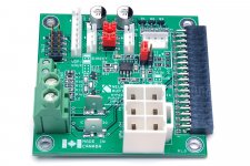
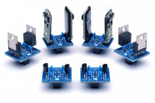
The Purifi 1ET400A / Hypex NC500 Input Buffer is exactly that: A buffer or gain stage intended for use with the Purifi 1ET400A and Hypex NC500 Class D amplifier modules.
The key features of the Input Buffer are:
The Input Buffer will be available by mid/late April. You can preorder yours and see the full specifications here: Neurochrome Purifi 1ET400A / Hypex NC500 Input Buffer Product Page.
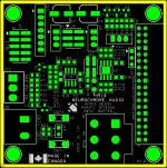
The pictures show a prototype (green board). The final version will provide identical performance and be Neurochrome Blue.
Tom
The key features of the Input Buffer are:
- Sonically transparent as evidenced by the ultra-low THD, IMD, and noise.
- Differential (balanced, XLR) input, which can easily be configured for single-ended (unbalanced, RCA) operation as well.
- Jumper-selectable gain: 0 dB and 13.2 dB for a total amplifier gain of 12.8 dB and 26.0 dB, respectively, when used with the Purifi 1ET400A.
- Gain can be further customized by adding a resistor (1206 size SMD and leaded/PTH supported).
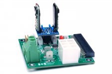
- Plug-and-play connection with Hypex SMPS1200 and future Purifi power supply.
- Opamp power supply: Use the AUX supply provided by the SMPS1200, or add your own regulator. A small daughterboard with support for the Hypex HPR/HNR, LM7812/LM7912, and LM78L12/LM79L12 is available as an accessory option.
- Status indicator LED output (NC500: CLIP and READY; 1ET400A: READY).
- Supports power supply shut-down in the event of amplifier failure when used with the Hypex SMPS1200 power supply.
- Speaker output is provided both on 6.3 x 0.81 mm quick-connect spades and a terminal block accepting up to AWG 10 (5.2 mm2) in size.
- Gold plated 4-layer PCB, 63.5 x 63.5 mm, RoHS compliant, Made in Canada.
- The buffer can be disabled by removing two resistors. A three-pin connector footprint provides direct access to the Purifi 1ET400A / Hypex NC500 input.
- A two-pin connector footprint provides access to the remote sensing pins of the Purifi 1ET400A / Hypex NC500.
The Input Buffer will be available by mid/late April. You can preorder yours and see the full specifications here: Neurochrome Purifi 1ET400A / Hypex NC500 Input Buffer Product Page.
The pictures show a prototype (green board). The final version will provide identical performance and be Neurochrome Blue.
Tom
Attachments
-
 PuriPex_P1p0_ASSY.jpg441.6 KB · Views: 2,963
 -
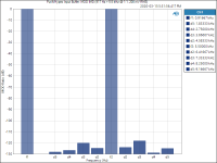
 Purifi_Hypex Input Buffer_ SMPTE IMD (60 Hz + 7 kHz @ 4_1, 2.0 V RMS).png26.5 KB · Views: 578
 -
 Purifi_Hypex Input Buffer_ MOD IMD (917 Hz + 5.5 kHz @ 1_1, 200 mV RMS).png26.3 KB · Views: 510
 -
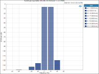 Purifi_Hypex Input Buffer_ DFD IMD (18+19 kHz @ 1_1, 2.0 V RMS).png23.3 KB · Views: 523
 -
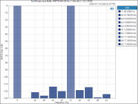
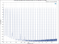 Purifi_Hypex Input Buffer_ Multi-Tone IMD (AP 32-tone, Vin = 2.0 V RMS, Ref._ 9.12 V RMS).png56.2 KB · Views: 577
 -
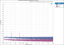 Purifi_Hypex Input Buffer_ Residual Mains Hum & Noise.png53.8 KB · Views: 558
 -
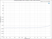 Purifi_Hypex Input Buffer_ THD+N vs Frequency (13.2 dB, 2 V RMS in, 60 kHz BW).png25.1 KB · Views: 2,195
 -
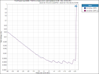 Purifi_Hypex Input Buffer_ THD+N vs Output Level, Load Impedance (0 dB, 1 kHz, 20 kHz BW).png33.5 KB · Views: 2,299
 -
 VReg_R1p0_ASSYs-2.jpg292.4 KB · Views: 2,267
 -
 PuriPex_wVreg.jpg226.8 KB · Views: 2,606
If one were considering a 3-channel system, is there a compatible recommended power supply for the 3rd channel? Or would the 1200 be enough? ...or 2 x 1200?
Hypex/Purifi are probably in a better position to answer that. I would think that the SMPS1200 is enough for three 1ET400A for music reproduction.
Just to confirm, you have setup the buffer similar to EVAL1 regarding the gain structure? 2V balanced input (between +/-) with a gain of 13.2db? Not 4V which more common on balanced systems?
i.e you have 1V max for RCA with 13.2db gain?
The default configuration of my Input Buffer has the same gain structure as the EVAL1. It also has slightly lower noise.
If you move a jumper you will get unity gain. If you move the jumper and add a resistor, you can set the gain, thus, the gain structure to your liking.
By default my Input Buffer has 13.2 dB gain (4.57x). The 1ET400A input specs are (Purifi data sheet Rev. 1.0):
- Differential input voltage (pos to neg input): 12 V
- Common-mode voltage: ±5 V
For the single-ended input, the max input voltage is limited by the common-mode voltage spec. So: 5/4.57 = 1.09 V peak (770 mV RMS).
Hmm... Thanks for bringing this up. Now is actually an excellent time to have this discussion (OK, three weeks ago would have been even better, but now is good.
") )
)I can easily change the 'custom' gain option to allow for 4 V differential, 1.5 V single-ended. That's the "fast to market" option. Unfortunately, this option would make the 'custom' gain option a bit harder to use, as you would need to remove an 0805 resistor and replace it with another 0805 resistor to change the gain.
Alternatively, I can redesign the Input Buffer to include a sort of "differential level translation". That would increase cost (maybe by $15), but would mean that the Class D amp always "sees" a differential input - even if the source connected to the Buffer is single-ended. That would be a nice market advantage.
I might be able to shave off a few cents from the board cost by eliminating the two 3-pin connectors for the optional external regulator and just leaving the 6-pin connector/jumper block in place. You can always connect a ribbon cable there if you want an external regulator.
Not to turn this into a design-by-committee project, but what do you folks think?
Tom
... Alternatively, I can redesign the Input Buffer to include a sort of "differential level translation". That would increase cost (maybe by $15), but would mean that the Class D amp always "sees" a differential input - even if the source connected to the Buffer is single-ended. That would be a nice market advantage ...
Tom
I really like this idea. I would buy a pair from you if you did this.
I already run my EVAL1 without gain due to my Cary SLP-05 preamp high output voltage and high efficient speakers.
I have also a DSP based multi-channel speaker setup that needs more control, and more optimal gain structure.
I look at including your buffer in a multi channel amp where I hope to easilly combine horn drivers and regular speakers. So it would be nice to have the availability to connect an external variable gain controller. Similar to what they included on the Vera Audio P400/1000
Would it be possible to have the gain resistors off the board?
.jpg)
I have also a DSP based multi-channel speaker setup that needs more control, and more optimal gain structure.
I look at including your buffer in a multi channel amp where I hope to easilly combine horn drivers and regular speakers. So it would be nice to have the availability to connect an external variable gain controller. Similar to what they included on the Vera Audio P400/1000
Would it be possible to have the gain resistors off the board?
You could easily implement that with a rotary switch and some resistors. I'm not planning to offer that as an option on the board, however. With the board the way it is, you could have three gain options: Unity, Gain 1 (default 13.2 dB), Gain 2 (custom). All that requires is an ON-OFF-ON type toggle switch.
Looks like Vera dropped the THX standard 26 dB gain. Interesting choice.
Tom
Looks like Vera dropped the THX standard 26 dB gain. Interesting choice.
Tom
Scratch what I said in Post #6. I'm not thinking about it the right way. As long as the single-input swings about zero, the common-mode voltage remains at 0 V, even with a single-ended input. So no design changes needed.
Sorry. My brain isn't firing on all cylinders today. I cracked my head pretty hard on the ice in a hockey game last Saturday. This is why goalies should not skate out... Anyway. The doctors and I are on top of it.
Redoing the math. The input voltage must remain within the ±12 V rails and the common-mode voltage within ±5 V.
This means the maximum differential voltage is 24 V (+12 on the non-inverting input and -12 on the inverting input). That means the max differential input voltage to the Input Buffer is: 24/4.57 = 5.25 V (3.71 V RMS).
With a single-ended input, the inverting input will be at 0 V. The voltage on the non-inverting input is limited by the ±12 V rails, so the max single-ended input voltage at the input to the Input Buffer is 12/4.57 = 2.62 V peak (1.85 V RMS).
Interestingly, the Purifi spec sheet says it takes 9.6 V RMS to drive the amp to clipping. 9.6 V RMS -> 13.6 V peak, which is beyond their own spec if a single-ended source is used. This means a single-ended source cannot drive the amp to clipping.
Just for reference: 9.6 / 4.57 = 2.1 V RMS, which would indicate that a gain of 4.57 (13.2 dB) is about perfect for single-ended operation. Those who use equipment with differential output would benefit from shaving 6 dB from the gain.
I think this boils down to whether you really, really want the last picoBell of power with a single-ended source. 2.62 V RMS, single ended, would result in 343 W. With a differential source you'd get over 400 W. That may be a selling point for some.
Tom
Last edited:
And just like that Revision 2.0 was born.
I was able to fit in a proper differential output in the Input Buffer layout. This means that those with single-ended (RCA) sources will be able to drive the Purifi/Hypex amp to clipping with a 2.0 V source without exceeding the input voltage spec on the Purifi modules.
I need to sleep on it and double-check everything, but I should still be able to hit the mid/end of April production target. I may have to increase the price slightly, but I need to do the math before I can commit to a new price. I will honour the price on all orders placed until I've done the math, i.e. order now and get your Rev. 2.0 Buffer at the current prices.
Aside from a possibly higher price is that I could not fit the legend for the jumper settings in the layout, so folks will have to ... (gasp) ... read the instructions before use.
Tom
Attachments
Is payment required in order to pre-order? The £ is rubbish at the moment.
A preorder is like a backorder. You have to fork over money and wait. You can order now and get the current price, or take the risk that my math (that I have yet to redo) warrants a price increase. I should know within the next couple of days.
The USD is strong right now. I guess people like 0% interest loans...
I'm collaborating with a guy in Germany (as I don't have a Purifi 1ET400A handy) who received the prototype boards yesterday. He is happy to report that everything is working. I had no doubt that the Buffer would work, but I do like trying things out in practice before throwing thousands of dollars at circuit board manufacturing and assembly.
Phenomenal as always Tom!
Thank you. Rev. 2.0 will be even better.
More good news: Even though Ontario, Canada has shut down all but "essential" businesses, my circuit board manufacturer is still running. It turns out they make boards for the healthcare industry, hence, is considered an "essential" business. That's excellent news for me. I should have boards in about 2.5 weeks. Then they're off to my assembly place in Calgary. Assuming Alberta hasn't shut down by then (and I think that's a reasonably fair assumption), that would mean boards in stock before the end of April.
Tom
Last edited:
The module looks nice and compact and well engineered.
I will be holding out for now though as while the above result look good I found my Bruno Butzey's Balanced Pre not to be able to drive the Purifi and sound as good as the experiments with the WHAMMY headamp modules do. BPBP uses same opamp as a buffer stage (LM4562) and in theory it should be capable of driving the Purifi modules.
One note also - the above measurements are into 4.4k and 3.6k but I measured the impedance to be 1.58k here. Or does your 3.6k mean that there is a 1.8k resistor in each positive and negative input leg?
Also having a socket for testing different opamps has really been very good, so it might be worth to consider supporting that on your module. Even with WHAMMY style module with opamp followed by class A MOSFET stage we hear many op-amps to add their small character into the mix. And this far it has not necessarily been the same opamp that sounds best in my system versus my friends system.
The module looks nice and compact and well engineered.
Thank you.
One note also - the above measurements are into 4.4k and 3.6k but I measured the impedance to be 1.58k
The input impedance of the Purifi 1ET400A is specified to 4.4 kΩ differential (2.2 kΩ from each input to ground). The Hypex NC500 is 3.6 kΩ differential (1.8 kΩ from each input to ground).
Similarly, my 4.4 kΩ differential load was comprised of two 2.2 kΩ resistors, one from each input to ground. The 3.6 kΩ load was comprised of two 1.8 kΩ resistors.
Also having a socket for testing different opamps has really been very good, so it might be worth to consider supporting that on your module.
Yeah, I suppose some would want to try different opamps. That's unfortunately not something I can support in production, though. The cost of getting the socket populated and stuffed with the default opamp would be quite high.
If you'd rather cook your own buffer, you can always remove two resistors and use the direct connection to the amplifier module input.
Tom
I am the lucky owner/tester of two rev 1.0 prototype boards by Tom.
You can see them added to my Purifi/Neurochrome build here:
 .
.
They work flawlessly with their buffer on (I only tried the 13.2 Db gain option), from the sonic point of view I did not hear significant differences w.r.t. the EVAL1 board, which means that they are probably both very transparent. I used the little daughterboard with two Hypex regulators on top.
These boards are really plug-and-play, so even an inept DIYer like me could make them work soon (we forgot to connect nAMPON to ground, so they initially they did not start, I then added a little jumper to connect the corresponding pins on one of the many connectors).
Later, I removed the two 0R resistors R18 and R19 that connect the buffer to the signal output pins, as you can see in the next pic:

I installed board-to-board pins on the provided holes and then soldered my Canare mini star quad to connect the output of the Universal Buffer. So my use of the boards is as a breakout board with space for a second regulation stage for modulator and comparator (I have a single Sulzer regulator providing ±18V, and then a pair HPR12/HNR12 per board bringing it down to 12V).
The result, in its fully over-engineered glory is this one
A couple more pics of the build, with its light blue plexiglass cover:
and
These boards are mostly for people doing monos (or three, five... channel amps), stereo builds with the two channels far from each other, or (most importantly) for people with single ended sources that want to have a proper and real differential output as an input to the 1ET400A modules (the latter feature is not present in the rev1.0 boards, but I only have balanced sources). None of these is my use case, and I could have continued to use the FE02 boards with bypassed buffers. But I could not pass the opportunity to help a designer that likes to do Engineering. Done. Right.
Among the cute features: the LEDs are on harnesses, with JST B3B connectors, so one can easily bring the green LEDs on the front of the amplifier, signalling proper operation through holes. I did not do that but I am keeping the LEDs in the amp.
You can see them added to my Purifi/Neurochrome build here:
They work flawlessly with their buffer on (I only tried the 13.2 Db gain option), from the sonic point of view I did not hear significant differences w.r.t. the EVAL1 board, which means that they are probably both very transparent. I used the little daughterboard with two Hypex regulators on top.
These boards are really plug-and-play, so even an inept DIYer like me could make them work soon (we forgot to connect nAMPON to ground, so they initially they did not start, I then added a little jumper to connect the corresponding pins on one of the many connectors).
Later, I removed the two 0R resistors R18 and R19 that connect the buffer to the signal output pins, as you can see in the next pic:
I installed board-to-board pins on the provided holes and then soldered my Canare mini star quad to connect the output of the Universal Buffer. So my use of the boards is as a breakout board with space for a second regulation stage for modulator and comparator (I have a single Sulzer regulator providing ±18V, and then a pair HPR12/HNR12 per board bringing it down to 12V).
The result, in its fully over-engineered glory is this one
An externally hosted image should be here but it was not working when we last tested it.
A couple more pics of the build, with its light blue plexiglass cover:
An externally hosted image should be here but it was not working when we last tested it.
and
An externally hosted image should be here but it was not working when we last tested it.
These boards are mostly for people doing monos (or three, five... channel amps), stereo builds with the two channels far from each other, or (most importantly) for people with single ended sources that want to have a proper and real differential output as an input to the 1ET400A modules (the latter feature is not present in the rev1.0 boards, but I only have balanced sources). None of these is my use case, and I could have continued to use the FE02 boards with bypassed buffers. But I could not pass the opportunity to help a designer that likes to do Engineering. Done. Right.
Among the cute features: the LEDs are on harnesses, with JST B3B connectors, so one can easily bring the green LEDs on the front of the amplifier, signalling proper operation through holes. I did not do that but I am keeping the LEDs in the amp.
Last edited:
Tom,
Impressive, that looks really nice!
I had thought the connector pinout was slightly different when comparing the 1ET400A and NC500 modules.
How are you handling that? Or am I wrong??
It is very nice to look at and hold it in the hands ;-) Even though the prototype boards I had were "Neurochrome prototype green" and not "Neurochrome blue".
The flexibility will appease DIYers, and paranoid people like me can easily have double regulation for the most sensitive part of the 1ET400a (modulators and comparators)!
The connector pinouts are the same, except that the Purifi does not signal CLIP, so it is unused there.
- Home
- Vendor's Bazaar
- Purifi 1ET400A / Hypex NC500 Input Buffer