Meet the Universal Buffer: A reference class analog preamp, made in Canada.
The Universal Buffer is an ultra high-end stereo analog subsystem. Each channel of the Universal Buffer features a differential input (which, by jumpers, can be configured as a single-ended input), and provides a buffered differential output and a buffered single-ended output. Its gain can be changed from the default 0 dB (unity) by adding a resistor. Furthermore, it can be configured for signal inversion.
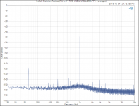
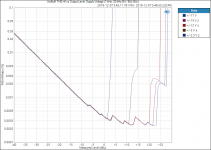
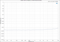
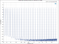
The reference class performance of the Universal Buffer is exemplified by its 137 dB dynamic range, abysmally low distortion (including intermodulation distortion), ultra-low noise, 130+ dB channel separation, high common-mode rejection ratio, as well as its ability to drive significant cable capacitance cleanly. All measurements of the Universal Buffer support my claim that this buffer is sonically transparent, and that any contribution to the sound quality made by the Universal Buffer is orders of magnitude below the audible threshold.
The Universal Buffer was primarily conceived as one piece of a reference class preamp. For example, a volume pot followed by a Universal Buffer would form a simple one-input preamp with both differential/balanced and single-ended/unbalanced outputs. Add another Universal Buffer upstream of the volume pot to add a differential input.
Similarly, the Universal Buffer can be used to add a differential input or output to your existing source or load, thus, it completely replaces my previous THAT Driver and THAT Receiver circuits.
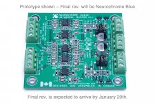
Except for the connectors, the Universal Buffer is all surface mounted components. Furthermore, two of the ICs have exposed pads under the IC package, thus, are challenging to solder. A good connection is needed for good performance. Due to this, I will only be offering the Universal Buffer as a fully assembled module.
The first batch of Universal Buffer boards is in production. I expect to have the boards in stock and ready to ship by January 20th, 2020. I have opened up for preorders. I will offer volume discounts for order quantities of 3+, 5+, and 10+.
For the full specifications and to preorder your Universal Buffer, please follow this link: Universal Buffer – Neurochrome
The image shows the final prototype. The production version will be identical, except it will be Neurochrome Blue like my other boards. The circuit design, PCB manufacturing, and PCB assembly were all done in Canada.
Tom
The Universal Buffer is an ultra high-end stereo analog subsystem. Each channel of the Universal Buffer features a differential input (which, by jumpers, can be configured as a single-ended input), and provides a buffered differential output and a buffered single-ended output. Its gain can be changed from the default 0 dB (unity) by adding a resistor. Furthermore, it can be configured for signal inversion.
The reference class performance of the Universal Buffer is exemplified by its 137 dB dynamic range, abysmally low distortion (including intermodulation distortion), ultra-low noise, 130+ dB channel separation, high common-mode rejection ratio, as well as its ability to drive significant cable capacitance cleanly. All measurements of the Universal Buffer support my claim that this buffer is sonically transparent, and that any contribution to the sound quality made by the Universal Buffer is orders of magnitude below the audible threshold.
The Universal Buffer was primarily conceived as one piece of a reference class preamp. For example, a volume pot followed by a Universal Buffer would form a simple one-input preamp with both differential/balanced and single-ended/unbalanced outputs. Add another Universal Buffer upstream of the volume pot to add a differential input.
Similarly, the Universal Buffer can be used to add a differential input or output to your existing source or load, thus, it completely replaces my previous THAT Driver and THAT Receiver circuits.
Except for the connectors, the Universal Buffer is all surface mounted components. Furthermore, two of the ICs have exposed pads under the IC package, thus, are challenging to solder. A good connection is needed for good performance. Due to this, I will only be offering the Universal Buffer as a fully assembled module.
The first batch of Universal Buffer boards is in production. I expect to have the boards in stock and ready to ship by January 20th, 2020. I have opened up for preorders. I will offer volume discounts for order quantities of 3+, 5+, and 10+.
For the full specifications and to preorder your Universal Buffer, please follow this link: Universal Buffer – Neurochrome
The image shows the final prototype. The production version will be identical, except it will be Neurochrome Blue like my other boards. The circuit design, PCB manufacturing, and PCB assembly were all done in Canada.
Tom
Attachments
-
 UNIBUFF_Proto_1p1.jpg452.6 KB · Views: 4,888
 -
 UniBuff_ Distortion Residual (1 kHz, 2 V RMS, UNBAL-UNBAL, 256k FFT, 8 averages).PNG45.1 KB · Views: 4,932
 -
 UniBuff_ THD+N vs Output Level, Supply Voltage (1 kHz, 20 kHz BW, BAL-BAL).PNG51.4 KB · Views: 4,534
 -
 UniBuff_ THD+N vs Frequency (2 V RMS, 60 kHz BW, BAL-BAL).PNG35.8 KB · Views: 4,504
 -
 UniBuff_ Multi-Tone IMD (AP 32-tone, 2.0 V RMS, Ref._ 2.0 V RMS).png55 KB · Views: 4,489
 -
 UniBuff_Transient_DIFF_4n7.png15.7 KB · Views: 969
 -
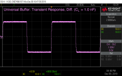 UniBuff_Transient_DIFF_1n0.png15.6 KB · Views: 777
 -
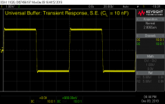 UniBuff_Transient_SE_10n.png20.4 KB · Views: 768
 -
 UniBuff_Transient_SE_4n7.png20.1 KB · Views: 834
 -
 UniBuff_Transient_SE_1n0.png20.2 KB · Views: 1,737
Cool. Looks very useful. What are the limits of the buffer? Could you use it for DAC IV duty or only use it after another Opamp does the IV duty?
I wouldn't configure it for I/V duty. That's not to say you can't do that, just that I'd optimize the circuit for I/V duty if that's what I needed.
What gain options are available with those resistors?
Whatever you'd like, basically. Only gains of unity or higher are supported, though.
Tom
Aha! I had to dig into the specs to see that it can be configured for lower voltages. I hope I can handle the two SM inductors.
I have to admit that a switching power supply was not what I would ordinarily choose to power a preamplifier. Would I be able to achieve the Universal Buffer's rated specs using the SMPS? Would some additional output filtering be required?
I have to admit that a switching power supply was not what I would ordinarily choose to power a preamplifier. Would I be able to achieve the Universal Buffer's rated specs using the SMPS? Would some additional output filtering be required?
I have just finally finished my Neurochrome Diff 8x2 Preamp.
Surface mount soldering was more difficult than I had anticipated.
And as I built it into a wooden box I worried about Pin 1 and grounding.
Other projects also got in the way.
Anyway it sounds brilliant and if it is any guide then this new preamp will be impressive.
Surface mount soldering was more difficult than I had anticipated.
And as I built it into a wooden box I worried about Pin 1 and grounding.
Other projects also got in the way.
Anyway it sounds brilliant and if it is any guide then this new preamp will be impressive.
I never had an input selector and volume control board, actually. The DIFF PRE 8x2 was essentially four THAT Receivers and one THAT Driver with a bunch of relays and a volume control. The five THAT circuits can be replaced by the UniBuff. I'd need to design an input selector board. That's a manageable task.
Tom
Tom

I would expect that an increase in gain will cause a slight increase in THD. That said, I would expect the THD+N to remain below the measurement limit of the APx525 even for gains over 20 dB.
I don't have measurements to confirm this, but can certainly play with that in January.
Tom
I don't have measurements to confirm this, but can certainly play with that in January.
Tom
If I understand things correctly (with my limited knowledge of electronics) I should be able to use the Universal Buffer in a high quality preamp that will provide me with years of fun listening.
I am currently in the process of building a low cost prototype of the B1 buffer, and a low cost prototype using cheap Chinese LM3886 kits from eBay. If I actually manage to produce some working boxes, I'll be looking to build some nicer versions as well (with LM3886DR for the power amp). I've understood that the B1 buffer uses a JFET before and a JFET after a volume pot with the JFET's functioning as buffers, so you would have this setup twice, once for each channel. The B1 has no gain, and the term buffer means matching the impedence of the components on both sides of the buffer if I've understood all of this stuff correctly.
How would one use the Universal Buffer in such a setup? I'm thinking something like this:
input selector - Universal Buffer - volume pot - Universal Buffer - output connectors
All of this assumes an unbalanced setup. Does it make sense?
- Home
- Vendor's Bazaar
- Universal Buffer achieving -140 dBc (0.00001 %) THD