In case I’d not mentioned in, one of the other 3886 amps of Tom's that I’ve heard is the more basic* “done right” - i.e. the baby without the LM49720 error correction. While nominally higher power, and with THD+N specs still well below what I used to think was “close enough for rock & roll” ") , the Modulus simply got more out of the way than I can remember in a long time. The 686 driving the Mark Audio MTMs at Dave Dlugos event in August certainly had me mesmerized.
, the Modulus simply got more out of the way than I can remember in a long time. The 686 driving the Mark Audio MTMs at Dave Dlugos event in August certainly had me mesmerized.
* I trust Tom, et al take that as no implied criticism, as it still incorporates the careful design & application considerations described in Taming the LM3886 Chip Amplifier
, the Modulus simply got more out of the way than I can remember in a long time. The 686 driving the Mark Audio MTMs at Dave Dlugos event in August certainly had me mesmerized.* I trust Tom, et al take that as no implied criticism, as it still incorporates the careful design & application considerations described in Taming the LM3886 Chip Amplifier
Last edited:
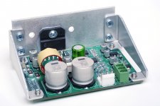
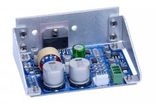
I just opened up for the introductory sale on the Modulus-186: Modulus-186: 65W composite amplifier achieving <-120dB THD
The sale will end by 23.59 Mountain Time (GMT-7) on November 30th. This will be the only sale on the Modulus-186 so get 'em while you can.
Tom
The sale will end by 23.59 Mountain Time (GMT-7) on November 30th. This will be the only sale on the Modulus-186 so get 'em while you can.
Tom
* I trust Tom, et al take that as no implied criticism, as it still incorporates the careful design & application considerations described in Taming the LM3886 Chip Amplifier
No worries on my end. "Basic" is fair. The LM3886DR is as good an implementation as I can get with the LM3886 by itself. For even better performance, the Modulus-series is where it's at.
Tom
The Mod186 doesn't look like it works very well if you would like to stack boards over each other to share a heat sink. All the connectors face upwards and the megafit is rotated 90 deg from the Mod686. You can use a vertical plug for the megafit, but the wire to the plug has issues on one side with the standoff and on the other with wires from the adjacent connector.
It depends on how tightly you want to stack the boards. I'm putting a Modulus-286 into an enclosure that has a mezzanine plate (for the power supply) located 36.5 mm above the chassis bottom. The plate overlaps the MOD286 board (which uses the same connectors as MOD186. The MOD286 is located as low on the heat sink as possible. This puts the bottom of the PCB at 9.9 mm above the chassis bottom (there's a bracket below the board) and the LM3886 about 1/3 up on the heat sink. There is enough space to get the connectors in there. You'll definitely have to bend the wires at the connector, but I think it'll work.
Of course if you want enough room that you can unplug the connectors within the board stack, you'll want more like 50 mm between boards. That won't work on a 2U heat sink, but should work on a 3U heat sink.
You can also rotate the boards 90º on the heat sink and "stack" them along the long dimension. You should be able to fit at least three boards on a 300 mm heat sink. The Modulus-186 is 3.55" wide, so you'll have to use a 3U heat sinks for that.
You are correct that going with a horizontal connector would make it easier to stack the boards. Unfortunately, that eats up valuable interior space in the chassis. Most builders seem to be more concerned with the additional space required for the horizontal connectors than eating into the space above the boards, so I went with vertical connectors. If you don't like it, you can always de-solder the connectors and solder the wire in directly.
Tom
Last edited:
One could also install the top board 'upside down' with the bottom of the lower board close to the bottom of the chassis and the bottom of the upper board toward the top of the heat sink. That would maximize space between the boards, the downside being somewhat less tidy cable routing.
The mounting bracket would help with the stacking of the boards. I am going to stack my Mod86 boards on a 3U heat sink which should work. I was just looking at how easy it would be at sometime in the future to swap the Mod86 boards with the Mod186 boards. The other heat sink will have a Mod686 mounted on it. I was thinking that mounting the boards vertically might be the way to go, but it would probably work better on the Mod186 instead of the Mod86 (due to the wires coming in from the end, although there should be space for them).
It is pretty cool watching the robot populate the boards. Took a tour of a plant today that had a robotic assembly line for their circuit boards. The SMD line wasn't running, but the through hole one was. At least I got to see all the equipment for the SMD line. It is real cool.
Do you have the hole spacings for this and the Mod286 boards? When I tap my heatsink to temporarily mount My Mod-86 modules, I can add a few more holes so I could mount either of the other two modules in the future.
Do you have the hole spacings for this and the Mod286 boards? When I tap my heatsink to temporarily mount My Mod-86 modules, I can add a few more holes so I could mount either of the other two modules in the future.
Do you have the hole spacings for this and the Mod286 boards? When I tap my heatsink to temporarily mount My Mod-86 modules, I can add a few more holes so I could mount either of the other two modules in the future.
I do have the hole spacings. I suppose I should put some sort of drawing together.
The holes are on 1.25" centres. I need to look up the dimensions from the last hole to the module edges though.
Tom
- Home
- Vendor's Bazaar
- Neurochrome Modulus-186: 40W (8Ω); 65W (4Ω) @ <-120dB THD Composite Amplifier Module