time to tell how the bisesik trafo play
my dac is JLsound AK4493,,with clock board and usb input
i have used 3 different output board
JLsound output board with Newclassd discrete opamp---absolute not bad
Mirand discrete output board---a little bit better
and now bisesik output trafo---by far the best
sound from the trafo..strong, dynamic,open,,nice for the ear,,lovely sound
i use the muting from JLsound output board,,so i have no click from the dac
well done bisesik
Best Bjarne
Thank you for your feedback!
Hello Ivan;
4493 needs Low pass filter after dac chip. With output transformer are we eliminate this? Or still we need it before or after transformer?
Hello Erkan,
Transformers have their own FR limitation, but in case of 1:1 transformer the LPF is a bit out from the desired ~70-80kHz and it is laying in the range over 120kHz I suppose. It is a theoretical things anyway, practice is more important. In general the answer depends on the particular setup. I do not use any additional LPF within my setup, as I hear details loss if I apply any capacitor across the output no matter what is the type of the DAC (R2R, delta-sigma, SDM). Using transformers of course. The best ever way for me is to use Ext2 filter in HQPlayer without any other LPFs (DAC is in the NOS-mode) as I do not know any other (HW-transports included) way to get the maximum from any DAC but HQP.
If you want to discover the impact of the additional LPFs I do recommend to read the Rasmussen' thread here on diyaudio forum. According to his research (if to be short) - it is needed to be at -0.7dB at 10kHz and -1.5dB at 20kHz. He recommended to use Zobbel network across the output. I have tried in the past to shunt with 1kOhm+nF(0.5nF to 5nF) to be at the needed points, but as I said earlier, HQP with Ext2 makes it much better and I do not use any extra LPF circuits.
Hi Ivan,
I have a little issue with the right channel output transformer for Ian's dual ES9038Q2M DAC. Seems like a high pitch ground loop on the right channel only (RCA). I swapped the cables left to right and the sound followed on the other channel. So I know it is the channel. I did solder the jumpers for RCA output and also removed the XLR jacks carefully due to space restrictions. What I don't know is if it is coming from the DAC board or the transformer board. I tried to separate the transformer output using ribbons but it didn't make any difference. Do you know what next I could check?
It is not loud and I have to be at 6-8 inches to hear it but I prefer silent to not lose micro details.
The transformer output sounds just amazing!
Do
Hi Do,
Try to connect the right RCA's ground not at the j6 jumper, but on another point, under the grounding screw of the "Tr1 Left" transformer for example or even without grounding the right channel. I mean try to find another grounding point of the Right RCA please instead of j6. Thank you!
Try to connect the right RCA's ground not at the j6 jumper, but on another point, under the grounding screw of the "Tr1 Left" transformer for example or even without grounding the right channel. I mean try to find another grounding point of the Right RCA please instead of j6. Thank you!
Any info on AD1865 implemetation?
I suspect that you know a little more about me, than what I have said here on this forum.

1865 is my lovely-favourite DAC right now
")
I believe there is no any chances to achieve such a resulting SQ rather than to use high-turns-ratioed transformers right after its I_out. OpAmps are just far-far away in this terms...
I suspect that you know a little more about me, than what I have said here on this forum.
1865 is my lovely-favourite DAC right now
I believe there is no any chances to achieve such a resulting SQ rather than to use high-turns-ratioed transformers right after its I_out. OpAmps are just far-far away in this terms...
Did you make a transformer like that and tested it? I have AD1865 with AD825 opamp, sound is excellent, but would like to try with trafo.
Yes I did. AD1865 have a weak current output compared to other DACs, that is why the best SQ possible is at level of 0.3-0.4Vrms out (after transformer) for AD1865 in SE-mode (regular stereo mode for single chip). Differential connection is better in that terms as 0.775V (0dBu) is a kind of standard for many (tube) amplifiers. The minimum load (input impedance of the next stage) should be 10kOhm as the turns ratio is 22.

Yes I did. AD1865 have a weak current output compared to other DACs, that is why the best SQ possible is at level of 0.3-0.4Vrms out (after transformer) for AD1865 in SE-mode (regular stereo mode for single chip). Differential connection is better in that terms as 0.775V (0dBu) is a kind of standard for many (tube) amplifiers. The minimum load (input impedance of the next stage) should be 10kOhm as the turns ratio is 22.
View attachment 878269
0.3Vrms? That is pretty low. I don't think I have a preamp with about 10, 11x gain. It can be made, but ....
I'm interested still, but it is a kind of a risk ... what is the price?
0.3Vrms? That is pretty low. ...
I would like to point one conceptual addition. I have addressed it a few times earlier. Again. The lower will be the i/v resistor seen by any (pure) current-type DAC, like AD1862/65, PCM63/1702/04 the better sound you will get as their output switches works worse when the voltage, converted from output current on the i/v resistor (impedance) is applied to them. Thus anybody should decide what is the sensetivity threshold in his own audiosystem is after DAC?.. I hear that in my system, the values upper than 20 Ohm of the seen impedance become affects on SQ much. It doesn't mean that this value is suitable for any other system (even <10 Ohm are known), but 20 Ohm is a quite common point of practice. Further, 1 mA*20 Ohm= 0.02V. To get 2V it is needed to use turns ratio of 1000! Just unreal to do within the needed FR. Moreover the input impedance of the next stage should be 2MOhms BTW for that. Going down to earth for trying with the widely existing practice of 47kOhm input impedance. The turns ratio for the targeted 20 Ohm impedance seen by DAC, should be ~1:50. The voltage (without internal losses) should be 1 V in this case. I am still trying to make such a ratio, but 22 is achieved for now.
The OpAmp approach is another story, DAC see around zero voltage across its output, but the targeted signal through its feedbacks... Meat grinder...
Hello Ivan;
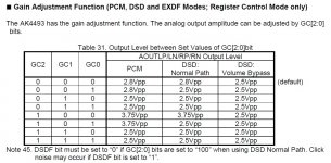
In 4493 there are couple of output voltage/gain options. Is it matters?
Note 14. The analog output voltage with 0dBFS input signal when GC[2:0] bits = “000” is calculated by the following formula:
AOUTL/R (typ. @0dB) = (AOUT+) - (AOUT-) = 2.8Vpp * (VREFHL/R - VREFLL/R)/5.
This expression is equivalent to 5.6Vpp and is differential and irrespective of ground reference or the Vcom bias voltage.
Note 15. The analog output voltage with 0dBFS input signal when GC[2:0] bits = “100” is calculated by the following formula:
AOUTL/R (typ. @0dB) = (AOUT+) - (AOUT-) = 3.75Vpp * (VREFHL/R - VREFLL/R)/5.
This expression is equivalent to 7.5Vpp and is differential and irrespective of ground reference or the Vcom bias voltage.
Attachments
Last edited:
I use the AK4493 in a few different DAC's I manufacture & it works very well with a 1:1 transformer which Ivan can supply. For the record his transformers sound excellent.
Using the AK4493 in hardware mode a 0dB signal will give you 2v rms out - perfect!
With the chip in software mode you also have higher output level option which gives 2.65v rms out.
Using the AK4493 in hardware mode a 0dB signal will give you 2v rms out - perfect!
With the chip in software mode you also have higher output level option which gives 2.65v rms out.

Hi Ivan,
FedEx package arrived yesterday.
So it left you on the 9th and was delivered here in South Australia on the 16th.
Expensive but quick.
Haven't had time for a good sit down listen with a glass of wine yet, but first impressions have put a smile on my face. Thank you for your efforts.
FedEx package arrived yesterday.
So it left you on the 9th and was delivered here in South Australia on the 16th.
Expensive but quick.
Haven't had time for a good sit down listen with a glass of wine yet, but first impressions have put a smile on my face. Thank you for your efforts.
Hi Ivan
I finally have my D3 TDA1541A DAC up and running in my system.
I have two D3 boards with TDA1541A running in dual/mono configuration using only some Caddock MK132 of about 110 Ohms as IV resistors.
It sounds very good, but I was wanting for the possibility of some more gain as one of my efficient horn speakers was recently knocked over and damaged. I have temporarily resorted to using a less sensitive open baffle speaker which I feel might benefit from some more gain.
As I contemplated a build of the CEN IV stage or ordering transformers I noticed Tubo had put his entire D3 project up for sale. I now own the transformers that you made for him.
I have been trying to figure out how to configure the transformers to use with my DAC.
I saw your schematic and related information in post #430.
To be honest, it is over my head. There are some electrical schematics that make sense to me, but I am not an electrical engineer and I simply don’t understand how things should be oriented for my application.
You mentioned that these transformers could be wired in a single ended application like mine to take advantage of differential output without having to worry about nulling the offset from the TDA1541A?
I really need an illustration of some sort showing how the jumpers, connections and any resistors (iv or otherwise) should be installed.
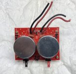
I have attached a picture of the transformers and board as I received them.
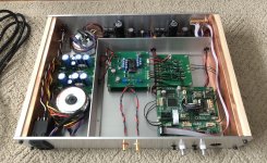
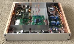
I’ve also attached a picture of my DAC so you can see how I currently have the outputs wired.
I was considering wiring the inputs to the transformer board to some RCA plug pigtails so I could just plug the transformers into the RCA output sockets on the back of my DAC as a test.
My IV resistors are mounted in dip sockets which allows me to change them out or even bridge the sockets so that they could be placed before or after the transformers. I was going to experiment with making some of my own wire wound IV resistors.
I am open to your suggestions as to what would be the simplest/best way to arrange things.
Any help you could offer would be greatly appreciated.
Regards
Kevin
I finally have my D3 TDA1541A DAC up and running in my system.
I have two D3 boards with TDA1541A running in dual/mono configuration using only some Caddock MK132 of about 110 Ohms as IV resistors.
It sounds very good, but I was wanting for the possibility of some more gain as one of my efficient horn speakers was recently knocked over and damaged. I have temporarily resorted to using a less sensitive open baffle speaker which I feel might benefit from some more gain.
As I contemplated a build of the CEN IV stage or ordering transformers I noticed Tubo had put his entire D3 project up for sale. I now own the transformers that you made for him.
I have been trying to figure out how to configure the transformers to use with my DAC.
I saw your schematic and related information in post #430.
To be honest, it is over my head. There are some electrical schematics that make sense to me, but I am not an electrical engineer and I simply don’t understand how things should be oriented for my application.
You mentioned that these transformers could be wired in a single ended application like mine to take advantage of differential output without having to worry about nulling the offset from the TDA1541A?
I really need an illustration of some sort showing how the jumpers, connections and any resistors (iv or otherwise) should be installed.
I have attached a picture of the transformers and board as I received them.
I’ve also attached a picture of my DAC so you can see how I currently have the outputs wired.
I was considering wiring the inputs to the transformer board to some RCA plug pigtails so I could just plug the transformers into the RCA output sockets on the back of my DAC as a test.
My IV resistors are mounted in dip sockets which allows me to change them out or even bridge the sockets so that they could be placed before or after the transformers. I was going to experiment with making some of my own wire wound IV resistors.
I am open to your suggestions as to what would be the simplest/best way to arrange things.
Any help you could offer would be greatly appreciated.
Regards
Kevin
Attachments
- Home
- Vendor's Bazaar
- Output transformers for DACs