I try to elaborate a bit more and apologize for my very probable errors in the following.
If I'm not wrong, the pcm63 can deliver up to 2mA and, when connected to a Resistor for I/V conversion, works best if the R is around 15/20 Ohms. In that case, Vmax across the Resistor would be 30-40mV.
Since my pre sensitivity for line input is 126mV, I'd ideally need a 1:4 or 1:3 ratio if the R is on the primary, while if I'm not wrong your unit is 1:17.
So if I'd wire a R in parallel to the secondary of your transformer, assuming the trafo as ideal, the load "felt" by the source (the dac) would be Rp=Rs/289, so a Rs of 4.7KOhm would represent a perceived load for the pcm63 of around 16Ohm which should be fine.
Does this make sense or do you have other suggestions?
Thanks for your patience,
Stefano
Your calculations are good, but tin terms of PCM63 itself, the lower impedance it sees, the better result (in terms of THD, noise floor, etc.) can be achieved. I wonder but seems such a value of 15-20 Ohms relates to the wide practice of SUTs usage in the past, I don't know why many audiophiles stacked on such value. Let's call it - rational i/v impedance. OK, let it be. My own i/v resistor in TDA1541A is 2.5R for now btw (similar output current as from PCM63) and I am definitely hear the benefits within my DAC by lowering iv impedance.
The main question would be can you use such a benifits or not? I can guess that there is some noise floor limit (tube based circuits usually), in the next after transformers, amplification stage, and might be to dig deeper of such is not very profitable, I don't know (is up to you).
As you have indicated 2mA (peak value) output from PCM63, then let it be 126mVpeak of the targeted signal.
different SUTs:
1:3 at 21 Ohms (42mV) (lowest output impedance)
1:4 at ~16 Ohms (32mV)
1:8 at ~8 Ohms (16mV)
1:17 at ~4 Ohms (8mV) (steepest LPF/best THD)
Thanks,
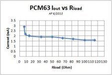
in a thread about pcm63 I got a couple of images (credits to original author) about the "ideal" value of load resistor for this dac.
Wouldn't too low a value (2.5R) make the pcm63 suffer in supplying the needed current?
Stefano
in a thread about pcm63 I got a couple of images (credits to original author) about the "ideal" value of load resistor for this dac.
Wouldn't too low a value (2.5R) make the pcm63 suffer in supplying the needed current?
Stefano
Attachments
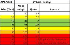
Thanks for sharing such measurements. I do not know why such a resistor value called as "ideal", but I know based on AD1862 that 7.5Ohm i/v resistor has impact (distortion) at -100dB.Thanks,
in a thread about pcm63 I got a couple of images (credits to original author) about the "ideal" value of load resistor for this dac.
There was no any issues in practice. The lower the seen imp, better LF response at least.Wouldn't too low a value (2.5R) make the pcm63 suffer in supplying the needed current?
Probably the best answer could be the answer for question: what impedance was seen by PCM63, within datasheet measurements (using OPs)?

.
Last edited:
Hello,
I control the volume of my DAC directly in the AK4493 chip. As I am not going louder than -24dB, I would like to attenuate the output signal by 24dB and thus use the full digital scale. What would be the best solution? A voltage divider bridge on the secondary of the transformer? What would be the most relevant resistor values?
Nounouchet
Dual Mono ES9038pro using Ivan's output transformer.
Dual Mono Buffalo III SEpro
I have built a dual mono ES9038Pro using 2x Buffalo III SEpro DAC board. For details please see the link for description.
I have read many comments that you don't need dual mono for the ES9038pro dac chip as it has very high current output already.
Well my dac, with dual mono setup, it outperforms the single ES9038pro dac quite easily. In fact, it is quite a big improvement. (my single ES9038pro dac also use the same Buffalo III SEpro board and also use the same output tx from Ivan).
The Buffalo III SEPro board is a very well designed digital piece of equipment. It is so compact and yet you can customize the power supply in so many ways.
Ivan's output transformer is excellent suited for the ES9038Pro dac chip. This dual mono ES9038pro gives me the best DAC sound I have ever heard.
Hi Henri,
Simply use a 3-resistor attenuation circuit instead of 10k across the secondary.

R1,R3 = 10k
R2=150k
This will attenuate your signal by -24dB.
p.s. if you need other tahn 10k input/output impedances (they can be different as you want), tell me for recalculation.
p.s.2. transformer do not steal the power of signal for attenuation, it just transforms the impedances (power approx. remains the same), whereas resistors steals the signal as dissipate it as a heat. That is the difference.
Simply use a 3-resistor attenuation circuit instead of 10k across the secondary.
R1,R3 = 10k
R2=150k
This will attenuate your signal by -24dB.
p.s. if you need other tahn 10k input/output impedances (they can be different as you want), tell me for recalculation.
p.s.2. transformer do not steal the power of signal for attenuation, it just transforms the impedances (power approx. remains the same), whereas resistors steals the signal as dissipate it as a heat. That is the difference.
Last edited:
Hi Alan,
Thank you for message!
Tell me please have you used resistor across the primary coil?
Thank you for message!
Tell me please have you used resistor across the primary coil?
Dual Mono ES9038pro using Ivan's output transformer.
Dual Mono Buffalo III SEpro
I have built a dual mono ES9038Pro using 2x Buffalo III SEpro DAC board. For details please see the link for description.
I have read many comments that you don't need dual mono for the ES9038pro dac chip as it has very high current output already.
Well my dac, with dual mono setup, it outperforms the single ES9038pro dac quite easily. In fact, it is quite a big improvement. (my single ES9038pro dac also use the same Buffalo III SEpro board and also use the same output tx from Ivan).
The Buffalo III SEPro board is a very well designed digital piece of equipment. It is so compact and yet you can customize the power supply in so many ways.
Ivan's output transformer is excellent suited for the ES9038Pro dac chip. This dual mono ES9038pro gives me the best DAC sound I have ever heard.
Hi Ivan,Hi Henri,
Simply use a 3-resistor attenuation circuit instead of 10k across the secondary.
View attachment 1003439
R1,R3 = 10k
R2=150k
This will attenuate your signal by -24dB.
p.s. if you need other tahn 10k input/output impedances (they can be different as you want), tell me for recalculation.
p.s.2. transformer do not steal the power of signal for attenuation, it just transforms the impedances (power approx. remains the same), whereas resistors steals the signal as dissipate it as a heat. That is the difference.
I don't use a resistor on the secondary (we discussed this earlier).
The input impedances of the amplifiers are 50K and 100K.
Is this scheme appropriate?
Thank you
nounouchet
What about resistor across the primary? Is it there or no as well?Hi Ivan,
I don't use a resistor on the secondary (we discussed this earlier).
The input impedances of the amplifiers are 50K and 100K.
Is this scheme appropriate?
Thank you
nounouchet
In general the presence of resistor across the primary or secondary (say, 10k) helps to linearize FR response (better at LF). The presence of resistors on both primary and secondary sides helps to transfer the signal power more efficiently. But the real need of resistors depends on the practical usage in the cirtain system, upon listening.
Recalcs for ~50k and ~100k
R1,R3=50k, R2=750k for 47k@-24dB
R1,R3=100k, R2=1.5M for 94k@-24dB
Last edited:
No resistor to the primary either.
Thank you for the values.
If i want -20dB, are the values correct ?:
50K: R1,R3=50k, R2=500k
100K: R1,R3=100k, R2=1000k
for -20dB it will be:
50K: R1,R3=55k, R2=495k
100k: R1,R3=110k, R2=990k
or
45.5K: R1,R3=50k, R2=450k
91k: R1,R3=100k, R2=900k
No. I have not tried. But I will later. It was already very good for 1x ES9038pro. But then Dual mono is even better with your transformer. I just want to listen and enjoy for a while before I try.Hi Alan,
Thank you for message!
Tell me please have you used resistor across the primary coil?
Hi Ivan,In general the presence of resistor across the primary or secondary (say, 10k) helps to linearize FR response (better at LF). The presence of resistors on both primary and secondary sides helps to transfer the signal power more efficiently. But the real need of resistors depends on the practical usage in the cirtain system, upon listening.
So with the attenuation I will have a resistor at the secondary!
Is there any type of resistor recommended or are the Vishay RN serie is good?
I already answered earlier like, no? Now I taking a look again - and see there is no my message. Is it a bug or what? Very strange... Well, okay. I'll post again.Hi Ivan,
So with the attenuation I will have a resistor at the secondary!
Is there any type of resistor recommended or are the Vishay RN serie is good?
The impact of resistor quality depends on the specific system. If in short then yes, the quality of the resistor before and after the transformer affects the quality and signature of the sound. In your case, you may ask yourself, do you hear the influence of different types of volume controls on the sound? Of course, the answer will be yes in most cases. In this context, I see no difference. Good results are obtained using resistors for audio applications such as AN, zfoil, rhopoint. Zfoils are very detailed and refined, but AN or Rhopoint can gives more analog-like sound.
Hi and first time poster here. I've worked on upgrading Doede's PCM1794 NOS DAC together with another diya member and things are shaping up so to speak. This is a complete overhaul. There's been reports of slight improvements going to 6 and even 8 paralleled DAC boards, so in my design, so I'll leave room for 8 boards.
Anyways, the reason I am here, now, is that I want to say thank you bisesik. My angle here is that besides working on the NOS dac, I am also working on a passive preamplifier which will use inductive volume control and these too use the noncrystalline core. The importance here is that compared to the resistivity type, be that IC or discrete, the inductive variant is a constant power device vs the resistive one which is a power converter. That is to say that the resistive type reduce both voltage and current and throw away the energy as heat, this leads to what can only be described as current compression at lower listening levels, restricting the dynamic range.
The inductive type, being a constant power device, does not throw away energy, it converts it - 1W in equals 1W out. So when the voltage is attenuated down the current increases. This will ensure full dynamic and current range and allow for micro details the other variant cannot offer.
It was in conjunction with preamp work which got me thinking. Knowing the value of the amorphous noncrystalline core for volume attenuation, it surely could not hurt to consider it as the choice for coupling transformer and well, bisesik, you beat me to it But I'm not against that, you have experience I do not and I value that. I also notice the coloration via the I/V resistors or the transformer and the later does make sense - aka, move the I/V resistors to the secondary - neat approach.
I'll stay in the background until further communication is needed.
Anyways, the reason I am here, now, is that I want to say thank you bisesik. My angle here is that besides working on the NOS dac, I am also working on a passive preamplifier which will use inductive volume control and these too use the noncrystalline core. The importance here is that compared to the resistivity type, be that IC or discrete, the inductive variant is a constant power device vs the resistive one which is a power converter. That is to say that the resistive type reduce both voltage and current and throw away the energy as heat, this leads to what can only be described as current compression at lower listening levels, restricting the dynamic range.
The inductive type, being a constant power device, does not throw away energy, it converts it - 1W in equals 1W out. So when the voltage is attenuated down the current increases. This will ensure full dynamic and current range and allow for micro details the other variant cannot offer.
It was in conjunction with preamp work which got me thinking. Knowing the value of the amorphous noncrystalline core for volume attenuation, it surely could not hurt to consider it as the choice for coupling transformer and well, bisesik, you beat me to it
But I'm not against that, you have experience I do not and I value that. I also notice the coloration via the I/V resistors or the transformer and the later does make sense - aka, move the I/V resistors to the secondary - neat approach.I'll stay in the background until further communication is needed.
- Home
- Vendor's Bazaar
- Output transformers for DACs