Prices for pair:
80H:80H = 170$.
20H+20H:80H = 190$
20H+20H:20H+20H = 210$
300H:300H= 260$
80H+80H:320H (same, as TioFrancotirador got) = 280$
80H+80H:80H+80H = 300$
Hi Ivan,
I'm very new to transformers,
could you please explain(briefly) the differences between these options:
80H:80H = 170$.
20H+20H:80H = 190$
20H+20H:20H+20H = 210$
300H:300H= 260$
80H+80H:320H (same, as TioFrancotirador got) = 280$
80H+80H:80H+80H = 300$
What are the differences in term of SQ?
I own a Ian 9038q2m double mono.
Which one should I use?
Are the prices for transformers + XLR/SE board or tansformers only?
Thank you very much.
Hi Terry.
It is high impedanced transformers - all of them are poorly suitable with ES90x8 DACs. They are for voltage-output DACs like AK4x9x (except 4499).
Within the Voltage DACs there is no straight answer what will better from aboved - it depends of the output capabilities of the exact DAC chip - it is more about the output impedance of DAC. One or two coils - depends on the connection schematics\implementation (diff\bal\se, etc. modes). The more inductance and\or coils quantity - the higher cost (of work\material).
For current-output DACs (like ES90x8) it is better to use another (step-up) transformers. The price is 150$ for pair. 170$ for ready to use i/v board (plug'n'play). Prices includes ww shipment.
Hi Terry.
It is high impedanced transformers - all of them are poorly suitable with ES90x8 DACs. They are for voltage-output DACs like AK4x9x (except 4499).
Within the Voltage DACs there is no straight answer what will better from aboved - it depends of the output capabilities of the exact DAC chip - it is more about the output impedance of DAC. One or two coils - depends on the connection schematics\implementation (diff\bal\se, etc. modes). The more inductance and\or coils quantity - the higher cost (of work\material).
For current-output DACs (like ES90x8) it is better to use another (step-up) transformers. The price is 150$ for pair. 170$ for ready to use i/v board (plug'n'play). Prices includes ww shipment.
Thank you for your answer Ivan.
I understand it better now.
")
I'll contact you by pm for ordering a ready to use transformers board.
It has xlr and SE outputs, right?
regards,
terry
Here is the schematic of the i/v board:
View attachment 779680
It is very interesting question. To avoid the usual answer that it acts like decoupling+LPF, I asked for TioFrancotirador to share his experience of using Teramoto transformers (same type of core material) with voltage type DAC. Hope it will be helpful.
One addition. All the next transformers will be made in PCB-style.
View attachment 770742
The center pin called shield and at diagram of i/v seems to connect with chassis.
Usually, we avoided to connect the ground of signal (SE) with the chassis because at the chassis we connect the main Earth for IEC Safety reasons.
Danger for ground loops!
What is the best practice for the center pin, from which part of transformer this pin is connected ?
This must be connected somewhere or it can be unconnected?
This pin galvanically connected to the can (shielding) - nothing extraordinary. Regular practice similar to Lundahl\Sowter\Any_other designs. The one only reason to use it - is the noise control. To use it or not - it is up to the designer (but it really helps to eliminate the grounding noise in most cases). This schematics relates to the i/v board only, usually it is simply connected ontop of the Ian's DAC and in this case we are a bit far from the finished enclosured device - usually it is standalone boards on the wooden plank
Plus and play Transformer for Ian dual 9038 q2m pro ,also can use with 9038 pro dac without mod ?
I am interested.
Suitable, except of i/v resistors in case of stereo configuration for 9038PRO (4 channels in parallel) - it is needed to lower their values in this case to be at the same output level as DM ES9038Q2M (9038PRO has 4 times stronger current output in this case).
This pin galvanically connected to the can (shielding) - nothing extraordinary. Regular practice similar to Lundahl\Sowter\Any_other designs. The one only reason to use it - is the noise control. To use it or not - it is up to the designer (but it really helps to eliminate the grounding noise in most cases). This schematics relates to the i/v board only, usually it is simply connected ontop of the Ian's DAC and in this case we are a bit far from the finished enclosured device - usually it is standalone boards on the wooden plank
For testing purposes a FFT can give the answer but from practice point of view, I think the best solution is a switch ON/OFF (shield to chassis) at the back side of case.
All I want to say is that the shielding pin if connected to the DAC chip' ground (to pin 11 of ES9038Q2M at least) - it helps to eliminate the noise (FFT proving it btw). All other cases including connection of "shielding can" to the chassis\enclosure\case - depends on the particular implementation and is out from schematic I shared above. It is up to the DIYer, who is building the DAC in particular case. Nobody prevent you to isolate these shieldings from the whole enclodure - just avoid the contact of "shielding can" with chasis - nothing extraordinary.
My setup is:
pi3b
ian's shield board (board with ground plane and pass through connectors)
ian's fifopi
ian's dual mono es9038 dac
bisesik transformer output board
I ordered ian's un-populated opamp output boards, but never built them up or tried them.
Still tweaking the digital part of the setup, but I have no urge to try another output stage, I'm really happy with my transformer based output.
Its easy to implement, you don't need to generate the +/- 12 or 15 or whatever for opamps.
IMHO, a bargain for what you get. I expect it would take a lot more work and/or money to get a better dac output stage.
Randy
Hi bisesik,
At the post #8 you have upload FR diagram with 10K load.
It seems in the range of 20-20KHz the FR response is flat and there is no need any LPF at the secondary.
I don't know how will be the FR Response with 192KHz sampling file, the trafo rises the upper part of FR Response usually.
At the post #36 you said
But, we know that the AK series 449x had a choice of 50/150KHz LPF on DSD only, to PCM files it simples some filters (linear phase sharp roll-off, linear phase slow roll-off e.t.c)
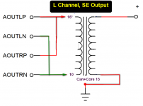
If we wanna to apply a LPF on secondaries, which is the best solution (I have attached two schemas about it) for voltage output trafo (80H:80H, 1:1)?
At the post #8 you have upload FR diagram with 10K load.
It seems in the range of 20-20KHz the FR response is flat and there is no need any LPF at the secondary.
I don't know how will be the FR Response with 192KHz sampling file, the trafo rises the upper part of FR Response usually.
At the post #36 you said
=There is more powerful LPF in case of ES (or AK) DACs - its inner Digital LPF. My aim is not to add additional LPF if possible.
But, we know that the AK series 449x had a choice of 50/150KHz LPF on DSD only, to PCM files it simples some filters (linear phase sharp roll-off, linear phase slow roll-off e.t.c)
If we wanna to apply a LPF on secondaries, which is the best solution (I have attached two schemas about it) for voltage output trafo (80H:80H, 1:1)?
Attachments

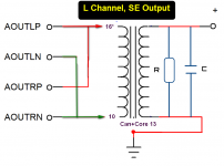
Hi lemon. Your questions are more for the particular DAC implementation at DIYer's side and I know cases when in the same setup one of my friends chosed to use Zobbel network at the secondary while the second guy concludes that he prefer without LPF. I remind - at the same time/setup. That is why I am a bit "confused" and understand that in your setup might be that sonically there will be no reason to use capacitors (or Zobbel) - I don't know. Technically the difference between cap only and Zobbel - the targeted shape of the LPF curve. Better to choose the desired by listening. Rasmussen methodic looks useful practically: -0.7dB at 10kHz and -2dB at 20kHz for example. This curve shape depends not only from the cap/res values, but from attached load impedance too. And it can be simply happend that within the available capacitor's type and its value (the higher value - the worse usually) will be better to use Zobbel (it has more flexible possiblity to change the curve than capacitor in parallel).
Last edited:
Bisesik thanks for the info.
I have thinking to use a 4 position micro-switch, at the first the zobel will be bypass and to the others 3 an appropriate combination for 10K, 20K and 40K load impedance.
I am thinking a very small silvered mica (330-470pF) for capacitor.
By the way, is that available the pin out of 1:0.5+0.5 trafo? I think this is the best setup for a true balanced output, isn't?
Of course it is possible, I have emailed to you.
Though it is intersesting question regarding true\pseudo balanced output, but it relates more to the DAC chip than to transformer. Can anybody identify clearly what the ES or AK DACs the outputs have? Are they true balanced or pseudo? What is the clear definition for true\pseudo balanced output? If you will take, say... PCM1794 then it is impossible to operate with - and + outputs without GND at all - is it the true BAL mode then? Then all other DACs like ES or AK are pseudobalanced? (their + and - outputs can be used separately from chip's gnd)..
Though it is intersesting question regarding true\pseudo balanced output, but it relates more to the DAC chip than to transformer. Can anybody identify clearly what the ES or AK DACs the outputs have? Are they true balanced or pseudo?
What is the clear definition for true\pseudo balanced output? If you will take, say... PCM1794 then it is impossible to operate with - and + outputs without GND at all - is it the true BAL mode then? Then all other DACs like ES or AK are pseudobalanced? (their + and - outputs can be used separately from chip's gnd)..I believe that all AK44xx series is a true differential output.
On page 63 of 4490's datasheet, says:
"The analog outputs are full differential outputs and 2.8Vpp (typ, VREFHL/R - VREFLL/R =5V) centered around VDDR/2and VDDL/2voltages..."
On trafos, never used the gnd connection, only the positive and negative output without any issue.
On page 63 of 4490's datasheet, says:
"The analog outputs are full differential outputs and 2.8Vpp (typ, VREFHL/R - VREFLL/R =5V) centered around VDDR/2and VDDL/2voltages..."
On trafos, never used the gnd connection, only the positive and negative output without any issue.
OK, if you have no any issues with noise, I agree .
It is more interesting to figure out why some DACs can operate with the single coil and others can not works like PCM1794.
Seems the DC-offset in 1794 have different polarity for + and - (in respect to GND) compared to AK/ES serries where the DC-offset polarity the same for both outputs (+&-).
. It is more interesting to figure out why some DACs can operate with the single coil and others can not works like PCM1794.
Seems the DC-offset in 1794 have different polarity for + and - (in respect to GND) compared to AK/ES serries where the DC-offset polarity the same for both outputs (+&-).
- Home
- Vendor's Bazaar
- Output transformers for DACs